|
Conditioner Pump Head Removal and
Replacement – Envoy
Tools needed:
Allen wench size 1/8” 3/8 Drive ratchet and 3/8” socket #T-25 Torx screw driver Card board Terry cloth towels Inch pound torque wrench (preferred but not necessary) 1/4” and 3/8” vinyl caps to plug hoses New pump head 14-100771-051 (Can be used for
conditioning or cleaner pumps)
Instructions:
1. Ensure
that the conditioner tank is no more than 1/3 full. (This first step is
optional to reduce spillage of conditioner) a. In the GUI navigate to the “Operators Screen”
Highlight the “Temperature Cycle” and turn it to “On”. b. While the pump is running, at the tank
connection, disconnect the suction tube that goes to the inlet on the pump. (See
Figure #1) Figure #1 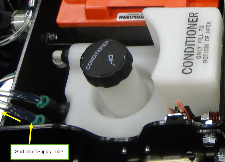
c. When conditioner stops flowing back to the tank,
turn off temperature cycle. Reconnect the suction tube on tank. 2. Removing the Conditioner Pump Assembly: a. Disconnect the electrical connections for the
Pressure valve and the Conditioner Pump. b. Remove the 3 bolts that mount the pump assembly
to the wall. Remove 1/8” Allen cap screw (Figure #2)
attaching the conditioner pump bracket to the frame.
Figure #2 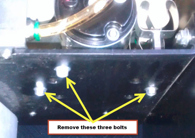 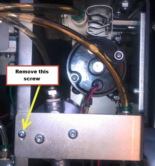
c. Take your hand and hold onto the bracket, use
your other hand to pry the shield away from the oil pump filter assembly
(Figure #3) and at the same time raising the pump assembly up and out.
Figure #3 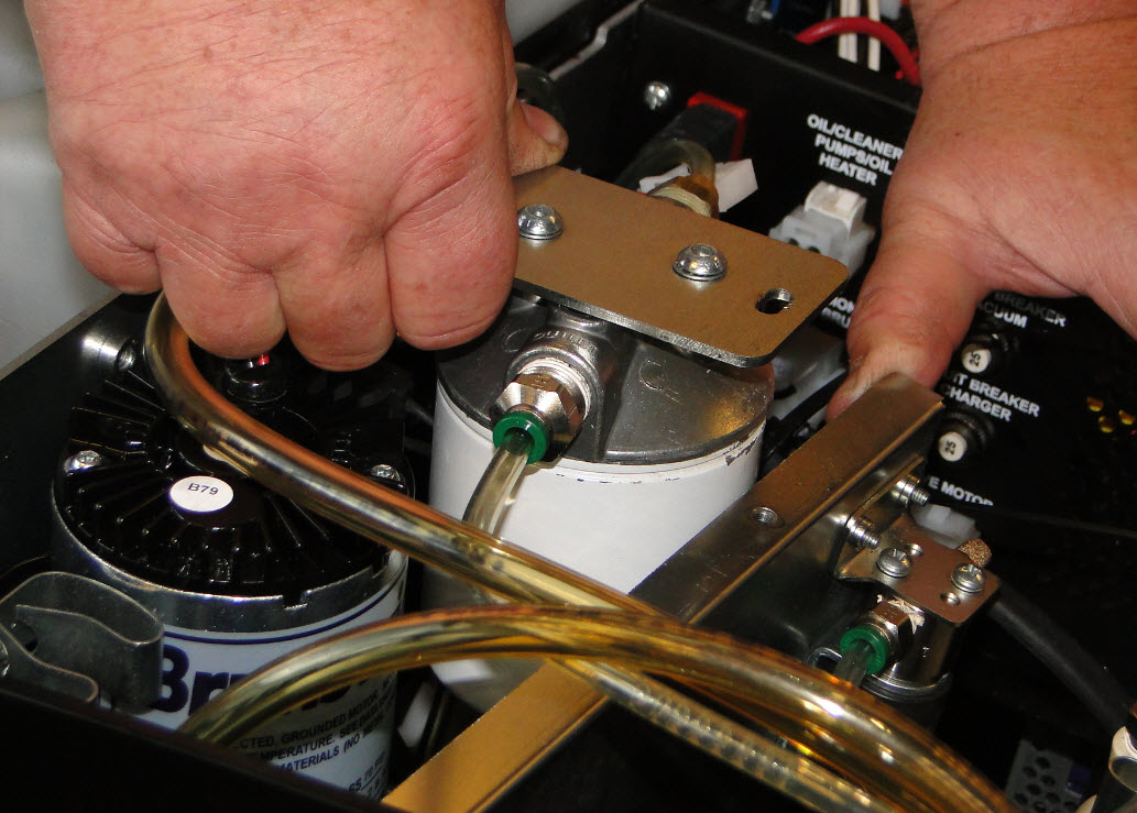
d. Flip entire pump bracket and assembly upside
down so that the 7 bolts that fasten the pump head are accessible (Figure #4). Note: Lay a piece of card board and terry cloth towel under the oil
pump assembly to catch oil drippings and to use as a support to work on.
Figure #4 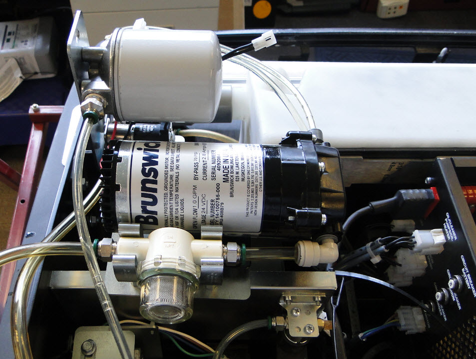
e. Disconnect the inlet and outlet fittings/Tubes
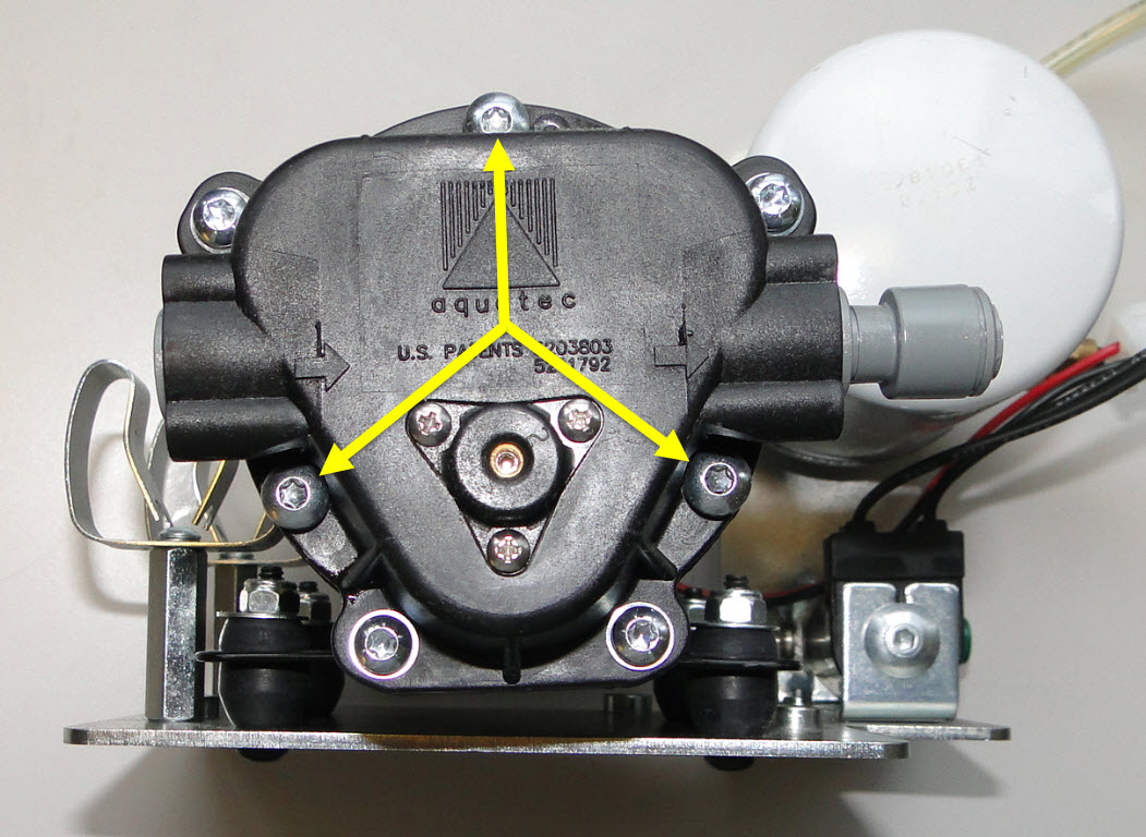
from the pump. Use the vinyl caps (if used) to plug the hose ends. f. Remove the 3 large Torx Head bolts (Figure #5) from
the pump using a T-25 screwdriver. Retain these bolts, Remove the pump head
from the pump motor.
Figure #5
 g. Place the new pump head 14-100771-051 on the
pump motor. Align the 3 bolt holes and finger tighten the bolts. 3. Torquing the bolts: a. Preferred method: using a torque wrench and a T-25
bit, gradually torque the bolts to 27 in-lbs. b. Then ensure that all 7 bolts are at 27 in-lbs.
Alternate method: Using a manual screwdriver with a T-25
bit, gradually tighten the 3 bolts until they are very tight by hand. Using any
wrench/lever or other mechanical means may over tighten and break the bolts or
damage the pump! Ensure that all 7 bolts are very tight by hand. Re-attach
the fittings/tubes to the pump. a. Re-attach the hoses back onto the new pump head.
b. Re-attach pump bracket to the frame.
c. Re-connect the electrical connections for the
pump and the pressure valve.
d. In the GUI navigate to the “Operators Screen”
Highlight the “Temperature Cycle” and press “Okay” to turn on the temperature
cycle. Check for leaks.
e. Continue to run temperature cycle until all air
has been removed from the conditioning system.
|