The Envoy conditioner pump head to motor bolts may not be
tight on some conditioner pumps. New Envoy lane machines and new conditioner pumps shipped between 2/1/2014 and 6/30/2014 may experience seepage of conditioner from the pump head to motor area. This can be fixed by tightening the pump head bolts to factory specifications. Below are the instructions to remove and replace the conditioner pump and tighten the pump head bolts. Tools Required: - 3/8” Drive ratchet and 3/8” socket, or 3/8” wrench
- 1/8” Allen wrench
- T20 Torx socket
- Torque wrench with Inch Pound or Newton Meter scale
Parts Required: None Procedure: Note: It is not necessary to remove any of the conditioner pump hoses for this procedure. 1. Relieve the conditioner pressure using the
lane machine GUI as follows: - Select “Maintenance” >
“Diagnostics” > “Conditioning.
- Highlight the “Oil Pressure Valve” button and press “Okay” to relieve the oil pressure to zero as shown on the GUI digital gauge.
- Check the analog gauge on the accumulator rail to verify zero pressure.
2. Locate and disconnect the
electrical connector for the conditioning pump and the oil pressure valve. 3. Remove the small 10-32 x
1/2” long Allen head screw that secures the cross bracket to the conditioner
pump oil/filter pan. Refer to Figure 1. 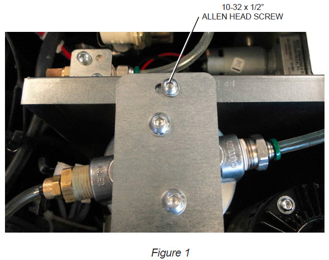
4. Remove the three
conditioning pump bracket bolts located on the outside wall next to the waste
tank. Refer to Figure 2. 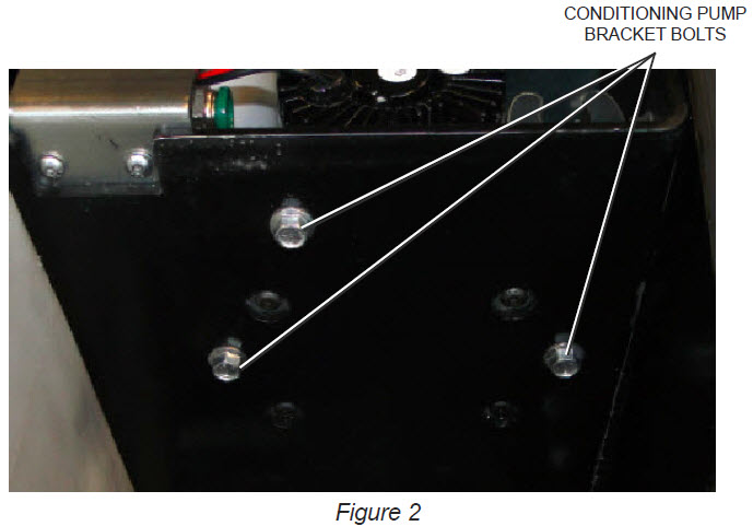
5. Push the oil pan wall away
from the bracket so that the complete assembly can be lifted up and out of the
oil pan tray. Refer to Figure 3. 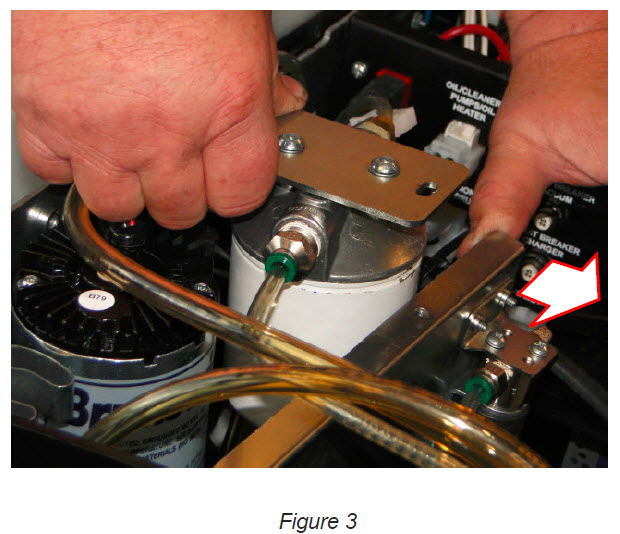
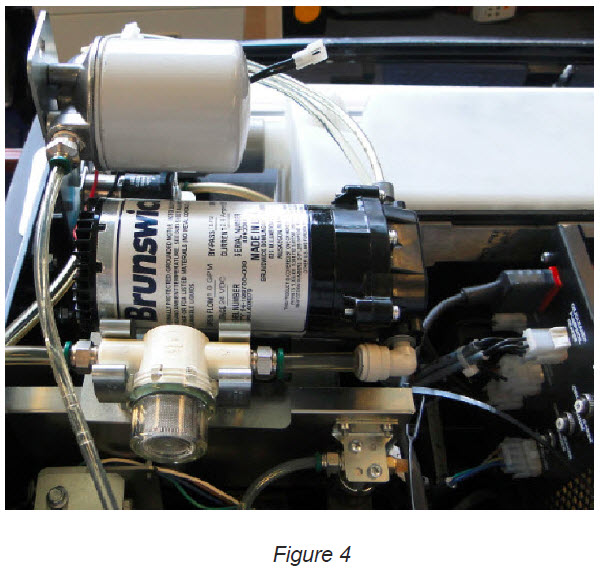
6. Lay the assembly across the dividing wall between the oil pan and center tub section. Refer to Figure 4.
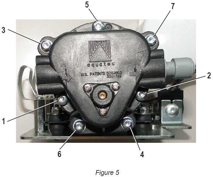
7. Using a torque wrench and T20 Torx socket, tighten the seven screws to 26-28 Inch pounds or 3.1 Newton Meter Nm. Start with one screw and alternate sides of the pump head when torquing the screws. Refer to Figure 5 for torquing sequence.
8. Reverse the pump removal
procedure (step 5 – step 2) to re-install the conditioner pump and bracket
assembly back into the machine. |