1. Brunswick A22
1.1. A22 Heater Ohm Measurements
Environment:
A22 heater
Applicable Version(s):
All
Procedure:
See attachment
Applicable Files:
'A22 Heater Ohm Measurements.pdf'
Revision Date:
10/01/2018 - Released to KB

 
1.2. Bad or Low Voltage on Electrical Enclosure Power Supply
Environment:
Lane Machine Electrical
Applicable Version(s):
All A22
Issue:
Bad or Low Voltage on Electrical Enclosure Power Supply
Cause:
No power to low voltage on electronic components (GUI and electrical enclosure electronics boards)
Solution:
See attachment
Applicable File:
'Electrical Enclosure Power Supply Check.pdf'
Revision Date:
09/27/2018 - Released to KB

 
1.3. Cleaning System
1.3.1. A22 How to Jump the Cleaner Pressure Sensor
Environment:
A22 Cleaning System
Applicable Version(s):
All
Procedure:
See attachment
Applicable Files:
'A22 How to Jump the Cleaner Pressure Sensor.pdf'
Revision Date:
10/16/2018 - Released to KB

 
1.4. Conditioning System
1.4.1. A22 Will Not Inject Lane Conditioner From A Live Downloaded Pattern, But Will Inject Conditioner From The Injector Function Test.
Environment:
A22 GUI
Applicable Version(s):
A22 Lane Machine
Issue:
Machine will not inject lane conditioner from any live pattern that was downloaded, but will inject conditioner properly within the injector test.
Cause:
All Zeros are entered in the custom value drop down menu.
Solution:
Make sure the custom values are entered for the type of lane conditioner being used. If a Brunswick lane conditioner is being used and it is not in the drop down menu, the values for the specific Brunswick lane conditioner will need to be entered into the custom values.
Revision Date:
03/10/16 - Released to KB
1.5. Graphical User Interface (GUI) A22
1.5.1. A22 GUI 2.01 Software Update
System:
A22 Lane Machine
Compatible Models:
All
Important:

The software updates are made available for the following circumstances:

  • Interim updates required to move a customer to an updated version.
  • Customer is unable to locate their disc to reinstall this version.
  • A software disc was damaged/missing in shipment for this version.
  • As a service pack for the customers current version.
Usage of these files to update a customer to a newer version other than the customer has purchased will constitute a breach of license, and will leave the customer ineligible for support until proper license fees are paid.
Zip File Download:
Sharefile Link
*Please make sure to unblock any files prior to extracting/installing.
Failure to do so can cause unexpected behavior, or prevent the system from running properly. Unblocking Files
Release Notes:
Included in zip file
Revision Date:
04/30/2020 - Released to Knowledgebase.

 
1.5.2. A22 Will Not Inject Lane Conditioner From A Live Downloaded Pattern, But Will Inject Conditioner From The Injector Function Test.
Environment:
A22 GUI
Applicable Version(s):
A22 Lane Machine
Issue:
Machine will not inject lane conditioner from any live pattern that was downloaded, but will inject conditioner properly within the injector test.
Cause:
All Zeros are entered in the custom value drop down menu.
Solution:
Make sure the custom values are entered for the type of lane conditioner being used. If a Brunswick lane conditioner is being used and it is not in the drop down menu, the values for the specific Brunswick lane conditioner will need to be entered into the custom values.
Revision Date:
03/10/16 - Released to KB
1.5.3. Authority22 GUI "Lost Power" Message or No Power
Environment:
Authority22 Lane Machine
Applicable Version(s):
All
Procedure:
The attached procedure will assist in diagnosing issue with the Graphical User Interface (GUI) on the Authority22 lane machine.
Applicable Files:
'A22_No_Power_to_GUI.pdf'
Revision Date:
10/01/2015 - Released to KB

 
1.5.4. Authority22 No Communication to GUI
Environment:
Authority22 Electronic Enclosure and GUI
Applicable Version(s):
All

Procedure:


  1. Turn off the red power toggle switch on the side of the electrical enclosure.
  2. Disconnect AC input power connector to the Electrical Enclosure.
  3. Remove all screws holding the cover of the electrical enclosure and remove the cover. Leave the emergency stop connector connected and move the cover to the side.
  4. Remove all connections on the right side of the electronic enclosure to the motor control board. (Upper Board ).
  5. Remove the two Phillips head screws securing the motor control board trey.
  6. Re connect the AC power input connector to the side of the electrical enclosure.
  7. Turn the red power toggle switch back to the on position. Pivot the motor control board tray up to expose the machine control board leaving all cables from the top board to the lower machine control board connected.


Locate the D 9 LED and note if it is lit or flashing. If it is not lit or flashing, the machine control board has failed and must be replaced.

Revision Date:
06/01/2017 - Released to KB

 
1.5.5. Blank GUI Display or White Vertical Lines
Environment:
Authority22 Lane Machines Only
Applicable Version(s):
2.0
Issue:
A black display, or a display with a 1” wide white scratchy vertical line from the top to the bottom.
Cause:
The cause of this is the Ferrite core that surrounds the 1” wide video display ribbon cable not having double sided tape installed during manufacture, or the tape has become weak and lost its adhesion. The Ferrite core is heavy and that weight will force the connection to the Motherboard to come loose or come off completely.
Solution:

Tools Needed:
Phillips screwdriver #2
11/32” Nut driver
1/16” thick or 1/8” thick two-way foam tape

To fix this you will need to follow the below steps. I suggest to take a picture of how the wiring is routed before disassembly.

1. Remove the 14 Phillips head screws mounting the top cover onto the GUI main body (Both sides and front) and place the cover to one side.

2. Mark the two black and white connectors for the Inverter with a permanent marker and remove. The marks are to associate the tops of the connectors.

Note: These two black and white connectors can be installed in either connector on the board, so marking them for position is mandatory.

3. Mark the top of the brown connector on the left hand side of the Inverter with a permanent marker and remove.

4. Unplug the black display cable, and the grey 1” wide video ribbon cable from the small video board in the lower left hand side.

5. Remove the GUI keypad ribbon cable. This cable has a locking tab that needs to be depressed to separate them.

6. Lay the GUI cover to the side and remove the three 11/32” nuts that are holding the mid plate cover onto the lower GUI base.

7. Once the mid plate cover is off, you will see the grey ribbon cable that you have disconnected earlier from the top area is connected to the bottom board in the back. This 'Viper board' as it is called, is the Motherboard. Notice in the below picture that there is no double sided tape and the Ferrite core is loose.

8. The ferrite core is connected to the video cable. There are times the core has come loose or has not been connected to the rear wall of the GUI to secure it. It should be secured to the back wall like in the picture below.

Note: You may find the video cable connection off of the Viper board. Reconnect this cable to the Viper board.

9. Secure this Ferrite core so that it will not put weight on the video cable you will need a 1” x 1” x 1/8” thick double sided adhesive foam strip to install on the Ferrite core.

10. Mount it to the back wall keeping the cable as loose as possible.

11. Install everything back in the reverse order. You may need to check the mid plate to see if there is a small piece of foam tape in the right hand corner of the slot for the video cable. If this foam strip is not there please add a piece to this corner so that the video cable does not rub against the mid plate in that corner. This could cause the cable to short and loss of video also. 

Note: When re-installing the mid plate be sure that the cable routing is correct, the cables have certain areas to route and will need to go into the same spot.

Note: When installing the cover make sure the keyboard ribbon cable is not hanging outside the cover, this may cause the cover to pinch the ribbon cable and fail the keyboard. It likes to squirt out the side.

12. Install the screws and power up the GUI.

Revision Date:
11/22/2016 - Released to KB

 
1.5.6. Making a Backup File for the Authority22 Lane Machine
Environment:
Authority22 Lane Machine Graphic User Interface Pattern and Settings
Applicable Version(s): All
Procedure:

This procedure is to help learn how to backup the patterns that have been created and saved, as well as copy over the settings installed into the GUI. This procedure should be done every time a pattern or a setting has been changed in the Graphic User Interface. This is to ensure that a customer can load his pattern and settings information into a new GUI if a exchange GUI is required.

1. Make sure the Graphic User Interface (GUI) is at the operator’s screen. (see Figure #1)

Figure #1 

2. Insert Thumb Drive (Flash Drive) into the USB port on the left hand side of the GUI. (see Figure #2)

Note: Make sure you use an empty Thumb Drive / Flash Drive with no folders or files on it. Leaving other lane machine 'Backup' folders on a thumb drive may cause inadvertent installation of another centers lane machines settings.

Figure #2 

3. The Import Data / Export Data screen will appear. Default is Export Data Press the green Okay to proceed to the next screen. (see Figure #3)

Figure #3


4. Now you are at the Export Data screen, press the green Okay button one more time. (see Figure #4)

Figure #4


5. You will see this screen for a few seconds, the words will be missing but it is okay(see Figure #5), then the Import Data / Export Data screen the words come back. At this time, you can remove the Flash Drive / Thumb Drive from the GUI. This part is now done.

Figure #5


Note: There is now a backup of patterns from the #1 bank, if you have more custom patterns in any of the other 4 banks #2 thru #5, you must select those banks when the Import Data / Export Data screen reappears, then selecting Export Data and choosing the next Backup number that has your patterns in it. You will have just one folder on the thumb drive called backup but all the patterns for each back number will be saved into this folder.

It is suggested to make a backup of you patterns on a regular basis and storing it on your personal computer in case they are erased.

Finding and Sending the “backup” files in email.

1. Insert your Thumb Drive / Flash Drive into your personal computer. Open your drive and look for a folder called backup. This folder should contain 19 files.


2. Double click on this 'backup' folder to open it. Again, you should see 19 files in this folder. Each one of these files will need to be sent in to techsupport@brunswickbowling.com via email (in one email) for us to troubleshoot the lane machine properly.


Note: You may also zip the folder 'backup' and send the zipped file instead of copying all 19 files over to an email.

3. Start by putting your 'backup' folder in a designated area of your computer like a folder for the center you’re working with. Then, right click on the folder 'backup' with the 19 files and choose 'Send to' (Figure #1) and then choose 'Compressed (zipped) folder'.


This will create a zipped folder right under the original 'backup' folder that is now zipped. 


4. Before sending email, add in the subject line the reference number your Brunswick Tech has given you in the email so that we can quickly reference your request. Example is below.


Revision Date:
02/23/2017 - Released from KB

 
1.6. Traction Drive System
1.6.1. Authority22 Traction Drive Motor Troubleshooting Procedure

Environment:
Authority22 Lane Machines
Applicable Version(s):
All
Procedure:

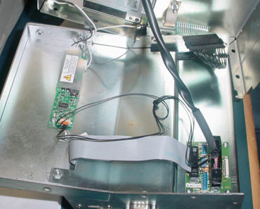
This procedure will help with troubleshooting the Authority22 Traction Drive Motor in the event that the motor will not run or the motor does not drive the machine correctly up or down the lane during operation. The Authority22 may also display an Encoder Sensor Error if the machine is not traveling down the lane at the correct speed.

The Authority22 Drive Motor is a DC motor and is rated at 90 VDC. The voltage to this motor is generated from the conversion of 115 or 230 VAC to DC voltages to run the motor. To accomplish this, AC voltage from the Motor Control Board is applied to the Regenerative Drive. It is then converted to DC voltages to allow the Traction Drive Motor to run in the correct direction and speed up and down during operation on the lane. Refer to Figure 1.

By taking voltage measurements at the Traction Drive Motor Connector, Regenerative Drive, Motor Control and Machine Control PCB the user can determine which part will need replacement.

Tools Required:

  • Digital Voltage Meter that is able to measure AC and DC Voltages.
  • Phillips Screwdriver #6 

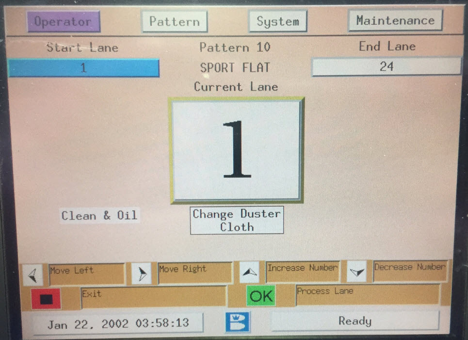
1. Checking Traction Motor for Operation.

  • Using the Graphical User Interface, (GUI) Keypad, navigate to Maintenance > Diagnostics > Drive. Refer to Figure 2.


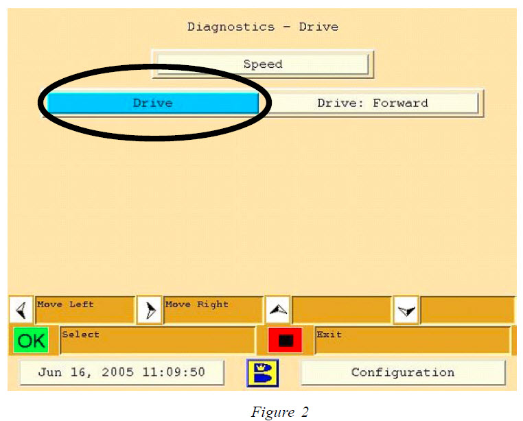
  • Using the GUI Keypad, select “OK” to run the Drive Motor Forward and Reverse. If the motor fails to run in either direction, check these items:


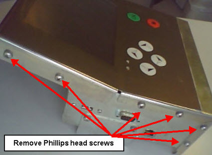
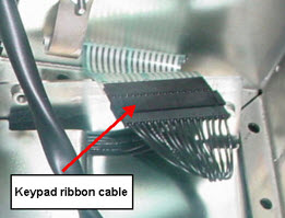
A. Looking from the T handle side, check the Traction Drive Motor Connection on the left hand side of the electrical enclosure. Check and make sure the connection is good and there are no wire pulled out of frayed. Follow the cable to the motor looking for pinched or cut wiring.

B. Check the fuse on the Motor Control PCB at location F16 inside the Electrical Enclosure. You will need a #6 Phillips head screw to remove the six screws from the top cover. Leave the cover connected to the emergency stop. This fuse is a 4.0 amp slow blow fuse 5mm x 20mm part # 14-860-214-000. If this fuse is not blown move to step #2 “Checking Drive Motor Resistance”.


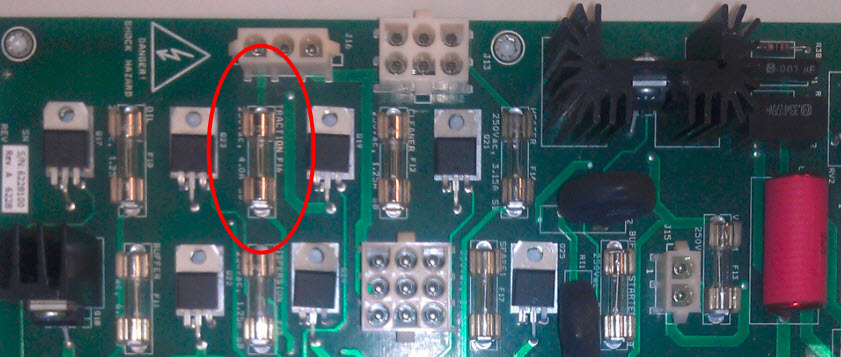
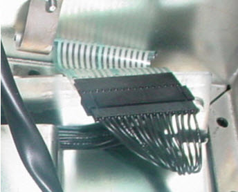
Note: When checking the fuse, refer to the following Warning.

WARNING!!!

Disconnect Power by moving the red toggle switch located on the side of the electrical enclosure to the down position and unplug the main power cord to the Authority22. Remove the GUI and set the GUI aside until the electrical cover can be removed. Remove the 6 screws that secure the top cover to the electrical enclosure. Remove the top cover leaving the emergency stop switch cable connected. Locate the traction drive motor fuse F16 on the motor control PCB and check the fuse for continuity with a meter set in the ohms position to determine if the fuse has been blown. Replace with 4 amp 250 volt slow blow fuse part # 14-860214-000 if necessary.

2. Checking Drive Motor Cable and Motor Resistance.

Locate the Traction Drive Motor Connector and disconnect it from the Electrical Enclosure. Using a voltage meter, select the Ohms setting on the meter and attach the red lead to the brown wire terminal inside the connector and connect the black lead from the meter to the blue wire terminal inside the connector. Resistance shown should be 4 to 5 Ohms. If no resistance is shown, the Traction Drive Motor or cable may be defective and must be repaired or replaced. If resistance is shown, reconnect the drive motor connector to the electrical enclosure and move to step #4 “Checking AC Voltage”.

Refer to Figure 3.


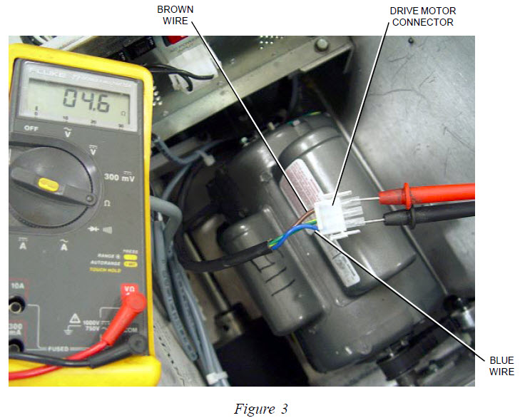
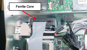
WARNING!!!

The Authority22 must be powered on to perform some of the remaining checks. Extreme caution is advised when taking voltage measurements and only qualified personnel should perform these readings.

3. Checking Drive Motor Voltage.

Reconnect the Drive Motor Connector back into the Electrical Enclosure. Install the red lead from the voltage meter to the brown wire location inside the connector, and the black lead to the blue wire location inside the connector. Select the VDC setting on the meter. Run the Traction Drive Motor in diagnostics as in Step 1. The reading should be +21 to +22 VDC when the motor is run in the forward direction and -21 to -22 VDC when the motor is run in the reverse direction.

If these voltages are correct in Step 3, this indicates that the DC voltages from the Regenerative Drive are correct and the drive motor should operate correctly. Recheck the Traction Drive Motor and cable resistance as described in Step 2 or replace the Traction Drive Motor.

If voltages are low or incorrect refer to Step 4 to troubleshoot the Regenerative Drive and the Motor Control PCB for correct operation.

4. Checking AC voltage to the Motor Control PCB and from the Motor Control PCB to the Regenerative Drive.

Locate the connector J12 located at the top of the Motor Control PCB. Using a voltage meter set to AC Volts, attach one lead to the black wire inside the connector and the other to the white lead inside the connector. With power applied to the machine, this reading should be 115 +/- 10% or 230 +/- 10% VAC depending on incoming voltage to the lane machine. If there is no voltage present, check incoming voltage to the Authority22. If voltage is present, check for the same voltages mentioned above at connector J16.

If there is AC voltage at connector J12 and no voltage at J16 replace the Motor Control PCB. If there is voltage at J16 continue to the next step.


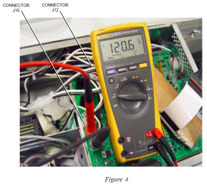
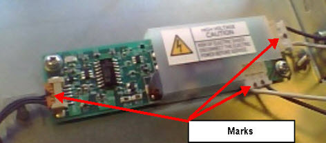
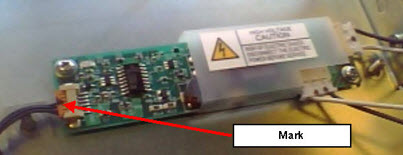
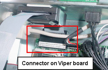
5. Checking Regenerative Drive DC Voltages.

There are 5 colored wires attached at the top of the Regenerative Drive. Refer to Figure 5. Taking voltage readings at these wire locations will tell if the Regenerative Drive has the correct voltages necessary to drive the Traction Drive Motor.

Note: Make sure all 5 wires are stripped and connected properly to the Regenerative Drive. Using a voltage meter, select the VDC setting and attach the black lead from the meter to the black common wire location, and attach the red lead from the meter to the green wire location at the Regenerative Drive. Refer to Figure 5. This should read -15 VDC while running the drive motor in the either direction.

Keep the black meter lead to the black wire location and attach the red lead to the red wire location. This should read +15 VDC while the motor is running in either direction.

If there is no voltage present in either direction, replace the Regenerative Drive.

6. Checking DC Voltage Signal to the Regenerative Drive.

Refer to Figure 5. Locate the Black Wire (Common) and the White Wire (Signal) at the Regenerative Drive. Using a voltage meter, select the VDC setting and attach the black lead from the meter to black wire location and the red lead to the white wire location.

While running the Drive Motor in diagnostics, check for +2 to +3 VDC while running the motor in the forward direction and – 2 to – 3 VDC in the reverse direction.

If there is no voltage present or the voltage is below -2 or +2 in the forward or reverse direction the Motor Control PCB or the Machine Control Board has failed, continue to Step 7 to determine if the Motor Control PCB or the Machine Control PCB will need replacement.

Note: As a final check to determine if the Regenerative Drive or the Motor Controller PCB is giving a incorrect signal, remove the white wire and re-test with step #6 with the red lead on the white wire and not connected, and the black lead connected with the black wire position.

If the signal is zero or under 2 volts forward or reverse, it is the Motor Controller PCB. If the signal voltage is 2- to 5 volts forward or reverse the problem is coming from the Regenerative Drive PCB.

Sometimes the Regenerative Drive will feed back voltage from the signal line causing incorrect signal readings. By disconnecting the white wire and testing we are getting a true reading from the Motor Controller PCB.

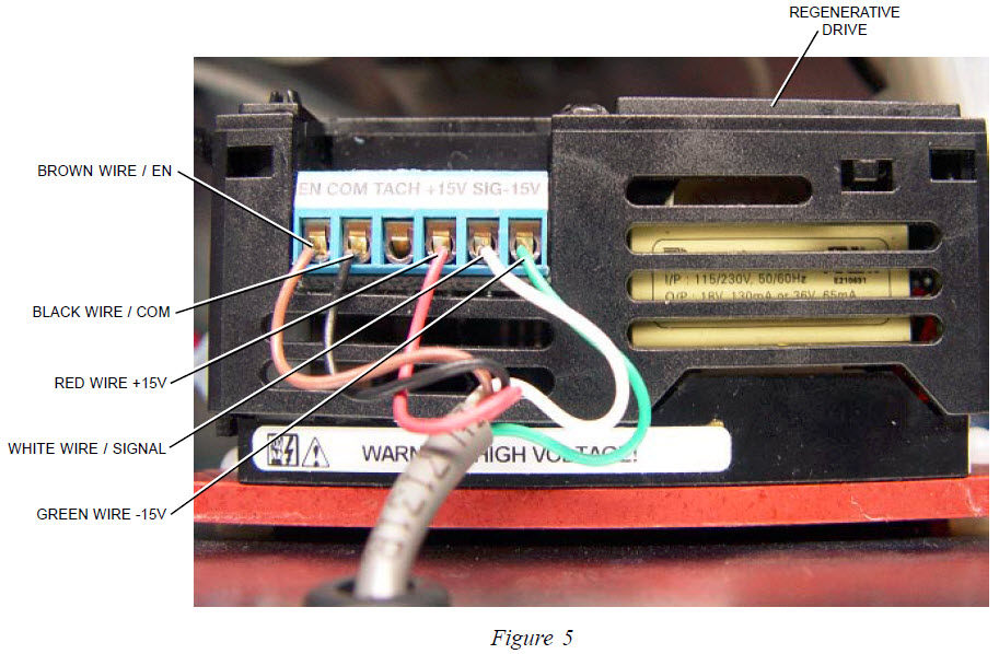
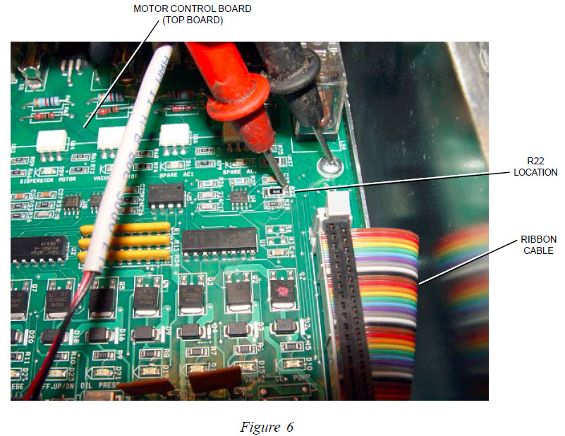
7. Checking for Correct Voltage from the Machine Control Board.

Before taking voltage reading, make sure the ribbon cable to the right of R22 is fully seated into the Motor Control PCB and the Machine Control PCB. Using a voltage meter, select VDC and attach the black wire lead to the Phillips head screw for ground, and the red lead to the top of R22. Refer to Figure 6. This reading should be between 2 to 5 VDC while running the Drive motor in the reverse or forward directions.

If there is no voltage present, or the reading is below -2 or +2 replace the Machine Control PCB, the bottom board inside the electrical enclosure. If the correct voltage is present, replace the Motor Control PCB.

Quick Notes: 

  • A weak signal from the machine controller PCB or motor controller PCB of -2 or +2 the machine will run slow. This signal must be above 2 volts + or – to obtain the proper speed.
  • Normally, if the drive motor will run one direction or the other this means you have 120 or 230 volts to the regenerative drive PCB.


Revision Date:
03/17/16 - Released to KB