1.1.2. Bad or Low Voltage on Electrical Enclosure Power Supply
Environment:
Lane Machine Electrical
Applicable Version(s):
All A22
Issue:
Bad or Low Voltage on Electrical Enclosure Power Supply
Cause:
No power to low voltage on electronic components (GUI and electrical enclosure electronics boards)
Solution:
See attachment
Applicable File:
'Electrical Enclosure Power Supply Check.pdf'
Revision Date:
09/27/2018 - Released to KB
1.1.3. Cleaning System
1.1.3.1. A22 How to Jump the Cleaner Pressure Sensor
Environment:
A22 Cleaning System
Applicable Version(s):
All
Procedure:
See attachment
Applicable Files:
'A22 How to Jump the Cleaner Pressure Sensor.pdf'
Revision Date:
10/16/2018 - Released to KB
1.1.4. Conditioning System
1.1.4.1. A22 Will Not Inject Lane Conditioner From A Live Downloaded Pattern, But Will Inject Conditioner From The Injector Function Test.
Environment:
A22 GUI
Applicable Version(s):
A22 Lane Machine
Issue:
Machine will not inject lane conditioner from any live pattern that was downloaded, but will inject conditioner properly within the injector test.
Cause:
All Zeros are entered in the custom value drop down menu.
Solution:
Make sure the custom values are entered for the type of lane conditioner being used. If a Brunswick lane conditioner is being used and it is not in the drop down menu, the values for the specific Brunswick lane conditioner will need to be entered into the custom values.
Revision Date:
03/10/16 - Released to KB
1.1.5. Graphical User Interface (GUI) A22
1.1.5.1. A22 GUI 2.01 Software Update
System:
A22 Lane Machine
Compatible Models:
All
Important:
The software updates are made available for the following circumstances:
Interim updates required to move a customer to an updated version.
Customer is unable to locate their disc to reinstall this version.
A software disc was damaged/missing in shipment for this version.
As a service pack for the customers current version.
Usage of these files to update a customer to a newer version other than the customer has purchased will constitute a breach of license, and will leave the customer ineligible for support until proper license fees are paid.
*Please make sure to unblock any files prior to extracting/installing.
Failure to do so can cause unexpected behavior, or prevent the system from running properly. Unblocking Files
Release Notes:
Included in zip file
Revision Date:
04/30/2020 - Released to Knowledgebase.
1.1.5.2. A22 Will Not Inject Lane Conditioner From A Live Downloaded Pattern, But Will Inject Conditioner From The Injector Function Test.
Environment:
A22 GUI
Applicable Version(s):
A22 Lane Machine
Issue:
Machine will not inject lane conditioner from any live pattern that was downloaded, but will inject conditioner properly within the injector test.
Cause:
All Zeros are entered in the custom value drop down menu.
Solution:
Make sure the custom values are entered for the type of lane conditioner being used. If a Brunswick lane conditioner is being used and it is not in the drop down menu, the values for the specific Brunswick lane conditioner will need to be entered into the custom values.
Revision Date:
03/10/16 - Released to KB
1.1.5.3. Authority22 GUI "Lost Power" Message or No Power
Environment:
Authority22 Lane Machine
Applicable Version(s):
All
Procedure:
The attached procedure will assist in diagnosing issue with the Graphical User Interface (GUI) on the Authority22 lane machine.
Applicable Files:
'A22_No_Power_to_GUI.pdf'
Revision Date:
10/01/2015 - Released to KB
1.1.5.4. Authority22 No Communication to GUI
Environment:
Authority22 Electronic Enclosure and GUI
Applicable Version(s):
All
Procedure:
Turn off the red power toggle switch on the side of the electrical enclosure.
Disconnect AC input power connector to the Electrical Enclosure.
Remove all screws holding the cover of the electrical enclosure and remove the cover. Leave the emergency stop connector connected and move the cover to the side.
Remove all connections on the right side of the electronic enclosure to the motor control board. (Upper Board ).
Remove the two Phillips head screws securing the motor control board trey.
Re connect the AC power input connector to the side of the electrical enclosure.
Turn the red power toggle switch back to the on position. Pivot the motor control board tray up to expose the machine control board leaving all cables from the top board to the lower machine control board connected.
Locate the D 9 LED and note if it is lit or flashing. If it is not lit or flashing, the machine control board has failed and must be replaced.
Revision Date:
06/01/2017 - Released to KB
1.1.5.5. Blank GUI Display or White Vertical Lines
Environment:
Authority22 Lane Machines Only
Applicable Version(s):
2.0
Issue:
A
black display, or a display with a 1” wide white scratchy vertical line from the top to the bottom.
Cause:
The
cause of this is the Ferrite core that surrounds the 1” wide video display
ribbon cable not having double sided tape installed during manufacture, or
the tape has become weak and lost its adhesion.The Ferrite core is heavy and that weight will force the connection to
the Motherboard to come loose or come off completely.
To fix this you will need to follow the below steps. I suggest to take a picture of how the wiring is routed
before disassembly.
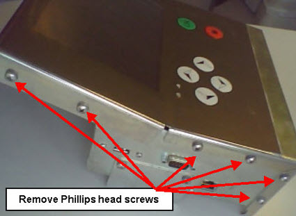
1. Remove the 14 Phillips head screws mounting the
top cover onto the GUI main body (Both sides and front) and place the cover to
one side.
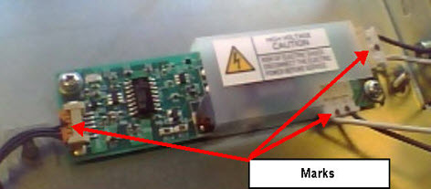
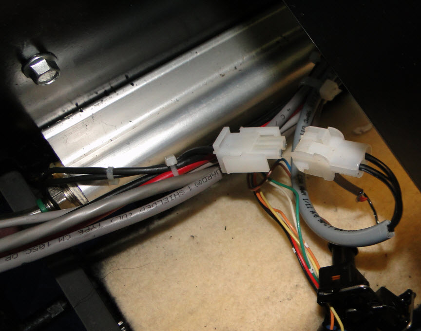
2. Mark the two black and white connectors for the Inverter with a permanent marker and remove. The marks are to associate the
tops of the connectors.
Note: These two black and white connectors can be installed
in either connector on the board, so marking them for position is mandatory.
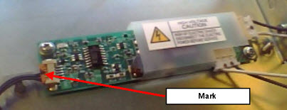
3. Mark the top of the brown connector on the left hand side of the Inverter with a permanent marker and remove.
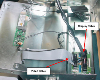
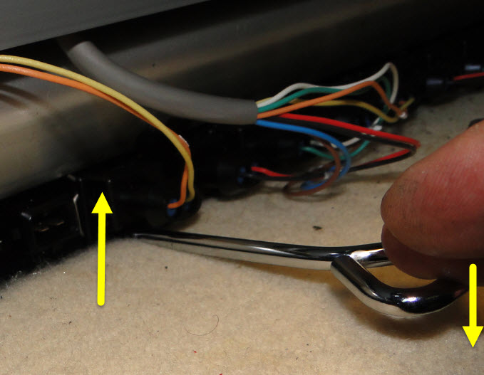
4. Unplug the black display cable, and the grey 1” wide video
ribbon cable from the small video board in the lower left hand side.
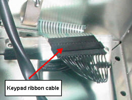
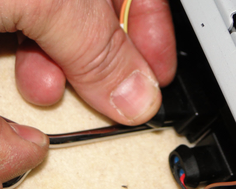
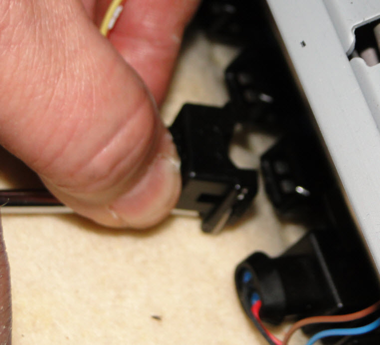
5. Remove the GUI keypad ribbon cable.
This cable has a locking tab that needs to be depressed to separate them.
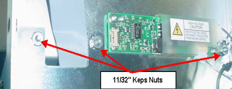
6. Lay the GUI cover to the side and remove the three
11/32” nuts that are holding the mid plate cover onto the lower GUI base.
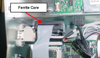
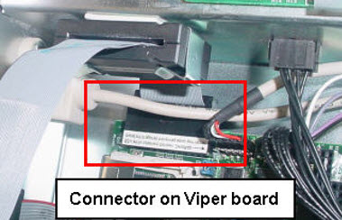
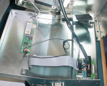
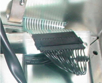
7. Once the mid plate cover is off, you will see the grey ribbon
cable that you have disconnected earlier from the top area is connected to the
bottom board in the back. This 'Viper board' as it is called, is the Motherboard.
Notice in the below picture that there is no double sided tape and the Ferrite core
is loose.
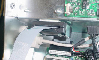
8. The ferrite core is connected to the video cable. There are times
the core has come loose or has not been connected to the rear wall of the GUI
to secure it. It should be secured to the back wall like in the picture below.
Note: You may find the video cable connection off of the
Viper board. Reconnect this cable to the Viper board.
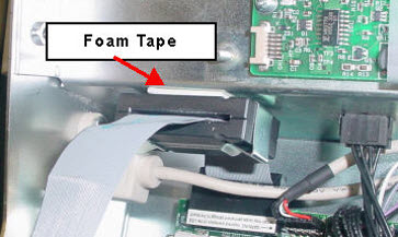
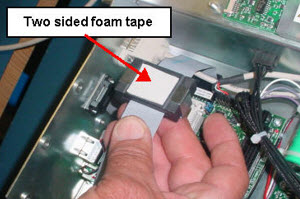
9. Secure this Ferrite core so that it will not put weight
on the video cable you will need a 1” x 1” x 1/8” thick double sided adhesive
foam strip to install on the Ferrite core.
10. Mount it to the back wall keeping the cable as
loose as possible.
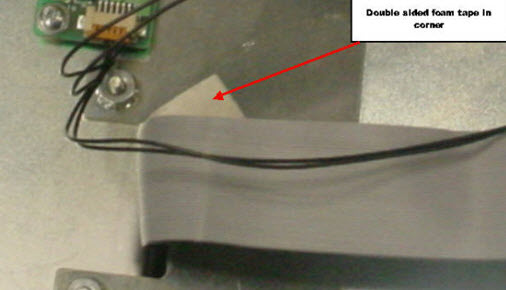
11. Install everything back in the
reverse order. You may need to check the mid plate to see if there is a small
piece of foam tape in the right hand corner of the slot for the video cable. If
this foam strip is not there please add a piece to this corner so that the
video cable does not rub against the mid plate in that corner. This could cause
the cable to short and loss of video also.
Note: When re-installing the mid plate be sure that the cable
routing is correct, the cables have certain areas to route and will need to go
into the same spot.
Note: When installing the cover make sure the keyboard ribbon
cable is not hanging outside the cover, this may cause the cover to pinch the
ribbon cable and fail the keyboard. It likes to squirt out the side.
12. Install the screws and power up the GUI.
Revision Date:
11/22/2016 - Released to KB
1.1.5.6. Making a Backup File for the Authority22 Lane Machine
Environment:
Authority22 Lane Machine Graphic User Interface Pattern and Settings
Applicable Version(s): All
Procedure:
This procedure is to help learn how to backup the patterns that have been created and saved, as well as copy over the settings installed into the GUI. This procedure should be done every time a pattern or a setting has been changed in the Graphic User Interface. This is to ensure that a customer can load his pattern and settings information into a new GUI if a exchange GUI is required.
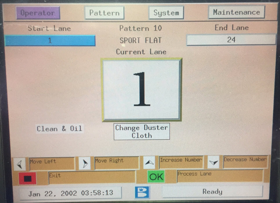
1. Make sure the Graphic User Interface (GUI) is at
the operator’s screen. (see Figure #1)
Figure #1
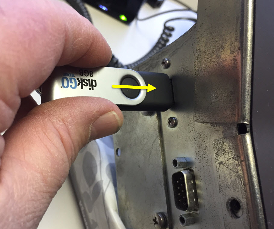
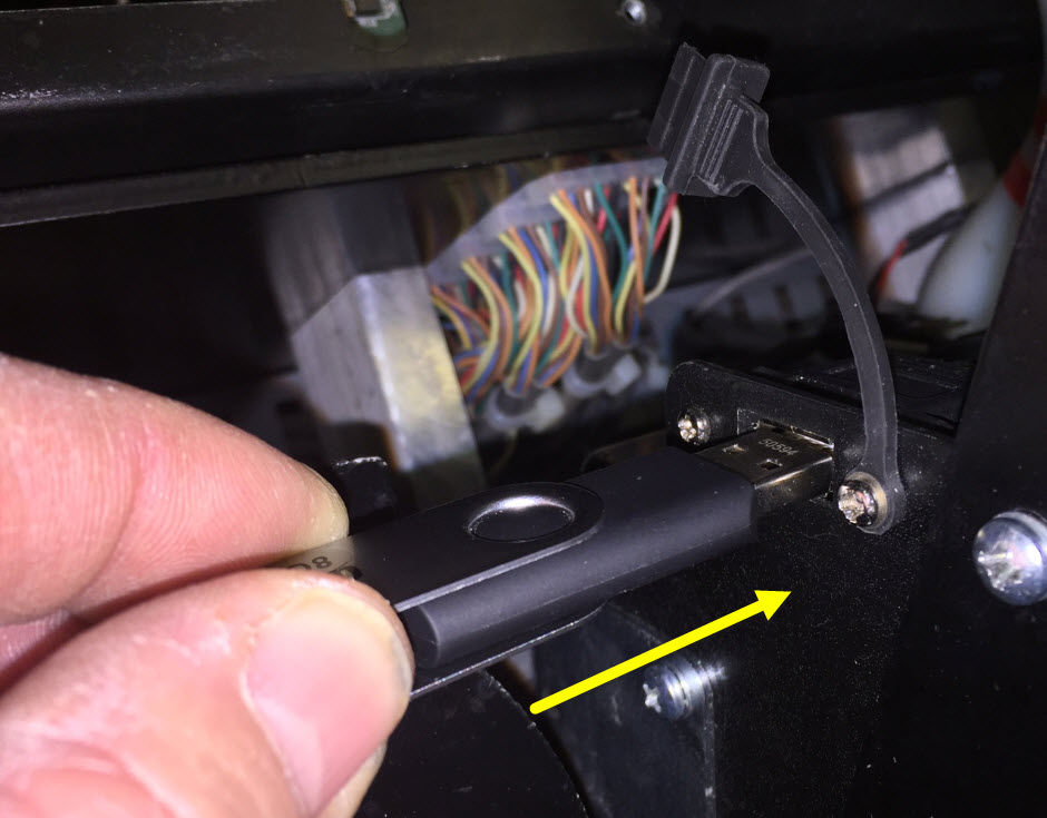
2. Insert Thumb Drive (Flash Drive) into the USB
port on the left hand side of the GUI. (see Figure #2)
Note: Make sure you use an empty Thumb Drive / Flash Drive
with no folders or files on it. Leaving other lane machine 'Backup' folders on
a thumb drive may cause inadvertent installation of another centers lane
machines settings.
Figure #2
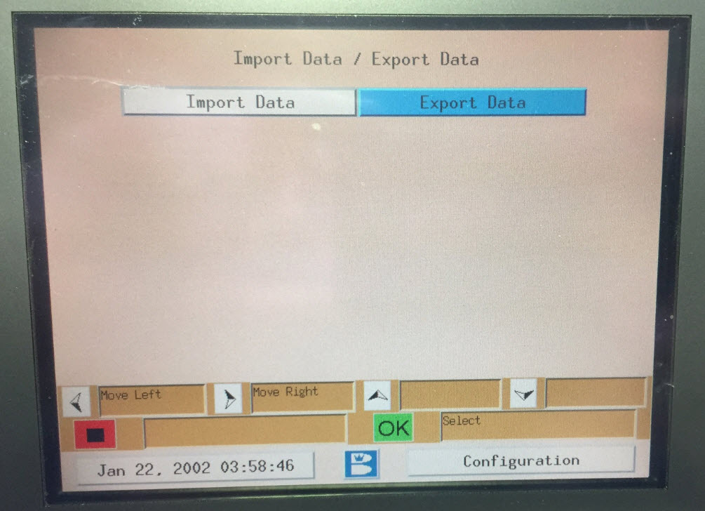
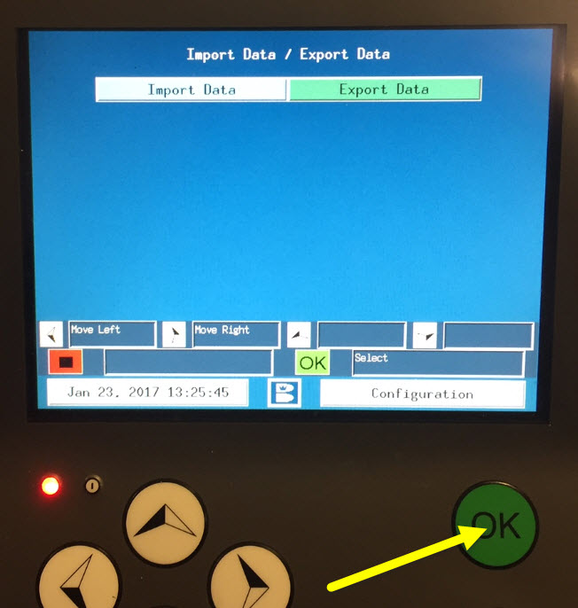
3. The Import Data / Export Data screen will
appear. Default is Export Data Press the green Okay to proceed to the next
screen. (see Figure #3)
Figure #3
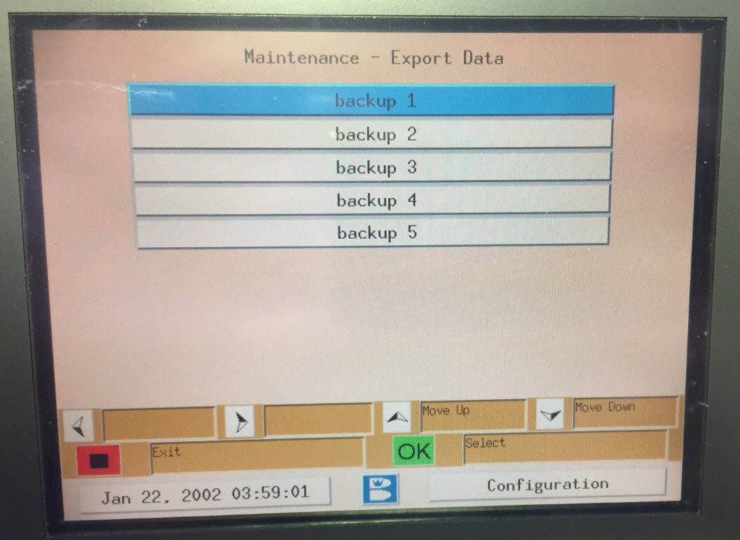
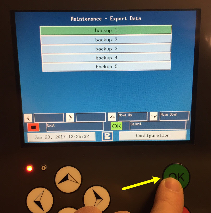
4. Now you are at the Export Data screen, press the green Okay button one more time. (see Figure #4)
Figure #4
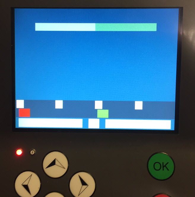
5. You will see this screen for a few seconds, the
words will be missing but it is okay(see Figure #5), then the Import Data / Export Data screen the words come back. At this time, you can remove the
Flash Drive / Thumb Drive from the GUI. This part is now done.
Figure #5
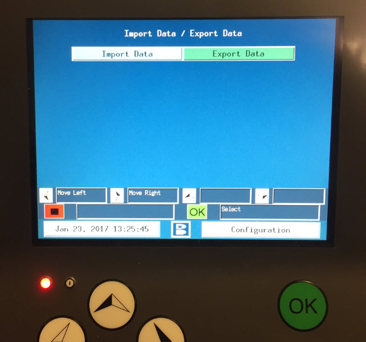
Note: There is now a backup of patterns from the #1 bank, if
you have more custom patterns in any of the other 4 banks #2 thru #5, you must
select those banks when the Import Data / Export Data screen reappears, then selecting Export Data and choosing the next Backup number that has your patterns in
it. You will have just one folder on the thumb drive called backup but all
the patterns for each back number will be saved into this folder.
It is suggested to make a backup of you patterns on a
regular basis and storing it on your personal computer in case they are erased.
Finding and Sending
the “backup” files in email.
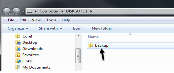
1. Insert your Thumb Drive / Flash Drive into
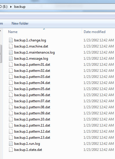
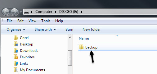
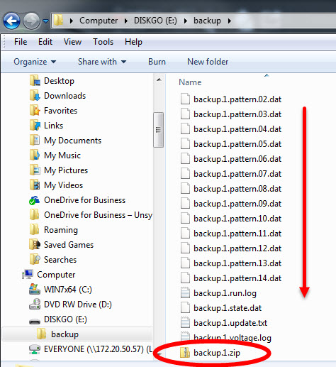
your personal computer. Open your drive and look for a folder called backup. This folder should contain 19 files.
2. Double click on this 'backup' folder to open it.
Again, you should see 19 files in this folder. Each one of these files will need to
be sent in to techsupport@brunswickbowling.com
via email (in one email) for us to troubleshoot the lane machine properly.
Note: You may also zip the folder 'backup' and send the zipped file instead of
copying all 19 files over to an email.
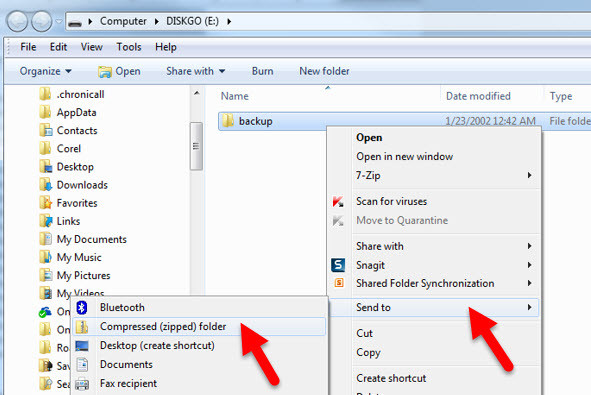
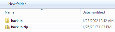
3. Start by putting your 'backup' folder in a
designated area of your computer like a folder for the center you’re working
with. Then, right click on the folder 'backup' with the 19 files and choose 'Send to' (Figure #1) and then choose 'Compressed (zipped) folder'.
This
will create a zipped folder right under the original 'backup' folder that is
now zipped.
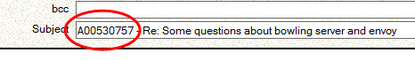
4. Before sending email, add in the subject line the
reference number your Brunswick Tech has given you in the email so that we can quickly reference your request. Example is below.
Revision Date:
02/23/2017 - Released from KB
1.1.6. Traction Drive System
1.1.6.1. Authority22 Traction Drive Motor Troubleshooting Procedure
Environment:
Authority22 Lane Machines
Applicable Version(s):
All
Procedure:
This procedure will help with troubleshooting the Authority22 Traction Drive Motor in the event that the motor will not run or the motor does not drive the machine correctly up or down the lane during operation. The Authority22 may also display an Encoder Sensor Error if the machine is not traveling down the lane at the correct speed.
The Authority22 Drive Motor is a DC motor and is rated at 90 VDC. The voltage to this motor is generated from the conversion of 115 or 230 VAC to DC voltages to run the motor. To accomplish this, AC voltage from the Motor Control Board is applied to the Regenerative Drive. It is then converted to DC voltages to allow the Traction Drive Motor to run in the correct direction and speed up and down during operation on the lane. Refer to Figure 1.
By taking voltage measurements at the Traction Drive Motor Connector, Regenerative Drive, Motor Control and Machine Control PCB the user can determine which part will need replacement.
Tools Required:
Digital Voltage Meter that is able to measure AC and DC Voltages.
Phillips Screwdriver #6
1. Checking Traction Motor for Operation.
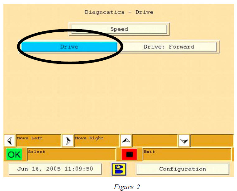
Using the Graphical User Interface, (GUI) Keypad, navigate to Maintenance > Diagnostics > Drive. Refer to Figure 2.
Using the GUI Keypad, select “OK” to
run the Drive Motor Forward and Reverse. If the motor fails to run in either
direction, check these items:
A. Looking from the T handle side, check the Traction Drive Motor Connection on the left hand side of the electrical enclosure. Check and make sure the connection is good and there are no wire pulled out of frayed. Follow the cable to the motor looking for pinched or cut wiring.
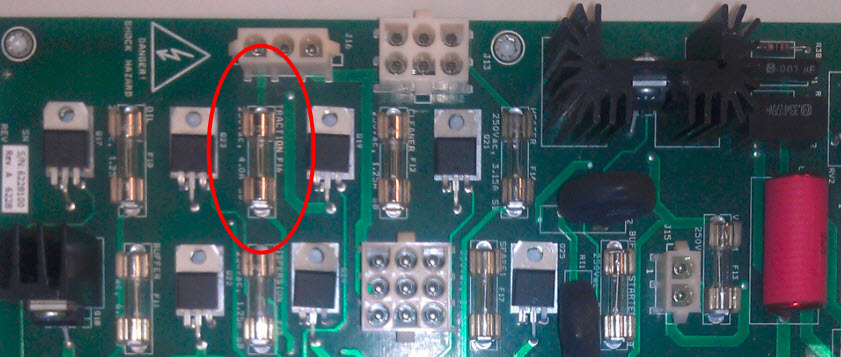
B.Check the fuse on the Motor Control PCB at location F16 inside the Electrical Enclosure. You will need a #6 Phillips head screw to remove the six screws from the top cover. Leave the cover connected to the emergency stop. This fuse is a 4.0 amp slow blow fuse 5mm x 20mm part # 14-860-214-000. If this fuse is not blown move to step #2 “Checking Drive Motor Resistance”.
Note: When checking the fuse, refer to the following Warning.
WARNING!!!
Disconnect Power by moving the red toggle switch located on the side of the electrical enclosure to the down position and unplug the main power cord to the Authority22. Remove the GUI and set the GUI aside until the electrical cover can be removed. Remove the 6 screws that secure the top cover to the electrical enclosure. Remove the top cover leaving the emergency stop switch cable connected. Locate the traction drive motor fuse F16 on the motor control PCB and check the fuse for continuity with a meter set in the ohms position to determine if the fuse has been blown. Replace with 4 amp 250 volt slow blow fuse part # 14-860214-000 if necessary.
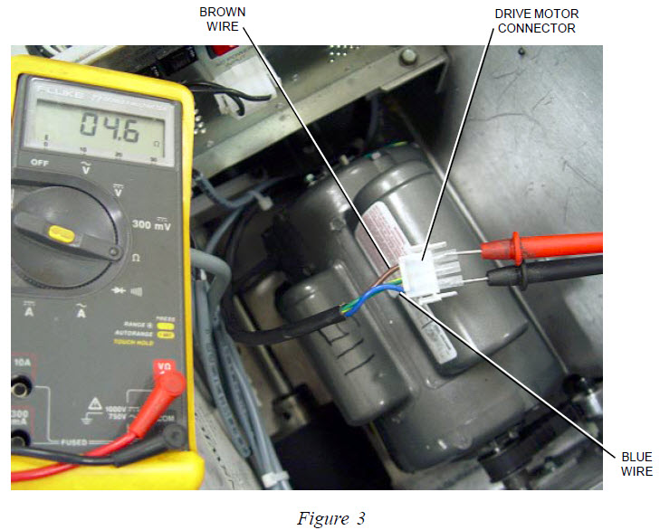
2. Checking Drive Motor Cable and Motor Resistance.
Locate the Traction Drive Motor Connector and disconnect it from the Electrical Enclosure. Using a voltage meter, select the Ohms setting on the meter and attach the red lead to the brown wire terminal inside the connector and connect the black lead from the meter to the blue wire terminal inside the connector. Resistance shown should be 4 to 5 Ohms. If no resistance is shown, the Traction Drive Motor or cable may be defective and must be repaired or replaced. If resistance is shown, reconnect the drive motor connector to the electrical enclosure and move to step #4 “Checking AC Voltage”.
Refer to Figure 3.
WARNING!!!
The Authority22 must be powered on to perform some of the remaining checks. Extreme caution is advised when taking voltage measurements and only qualified personnel should perform these readings.
3. Checking Drive Motor Voltage.
Reconnect the Drive Motor Connector back into the Electrical Enclosure. Install the red lead from the voltage meter to the brown wire location inside the connector, and the black lead to the blue wire location inside the connector. Select the VDC setting on the meter. Run the Traction Drive Motor in diagnostics as in Step 1. The reading should be +21 to +22 VDC when the motor is run in the forward direction and -21 to -22 VDC when the motor is run in the reverse direction.
If these voltages are correct in Step 3, this indicates that the DC voltages from the Regenerative Drive are correct and the drive motor should operate correctly. Recheck the Traction Drive Motor and cable resistance as described in Step 2 or replace the Traction Drive Motor.
If voltages are low or incorrect refer to Step 4 to troubleshoot the Regenerative Drive and the Motor Control PCB for correct operation.
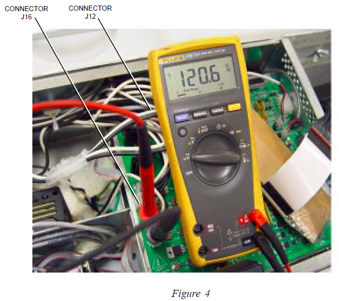
4. Checking AC voltage to the Motor Control PCB and from the Motor Control PCB to the Regenerative Drive.
Locate the connector J12 located at the top of the Motor Control PCB. Using a voltage meter set to AC Volts, attach one lead to the black wire inside the connector and the other to the white lead inside the connector. With power applied to the machine, this reading should be 115 +/- 10% or 230 +/- 10% VAC depending on incoming voltage to the lane machine. If there is no voltage present, check incoming voltage to the Authority22. If voltage is present, check for the same voltages mentioned above at connector J16.
If there is AC voltage at connector J12 and no voltage at J16 replace the Motor Control PCB. If there is voltage at J16 continue to the next step.
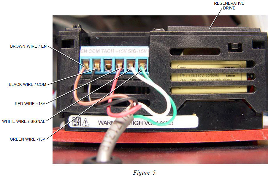
5. Checking Regenerative Drive DC Voltages.
There are 5 colored wires attached at the top of the Regenerative Drive. Refer to Figure 5. Taking voltage readings at these wire locations will tell if the Regenerative Drive has the correct voltages necessary to drive the Traction Drive Motor.
Note: Make sure all 5 wires are stripped and connected properly to the Regenerative Drive. Using a voltage meter, select the VDC setting and attach the black lead from the meter to the black common wire location, and attach the red lead from the meter to the green wire location at the Regenerative Drive. Refer to Figure 5. This should read -15 VDC while running the drive motor in the either direction.
Keep the black meter lead to the black wire location and attach the red lead to the red wire location. This should read +15 VDC while the motor is running in either direction.
If there is no voltage present in either direction, replace the Regenerative Drive.
6. Checking DC Voltage Signal to the Regenerative Drive.
Refer to Figure 5. Locate the Black Wire (Common) and the White Wire (Signal) at the Regenerative Drive. Using a voltage meter, select the VDC setting and attach the black lead from the meter to black wire location and the red lead to the white wire location.
While running the Drive Motor in diagnostics, check for +2 to +3 VDC while running the motor in the forward direction and – 2 to – 3 VDC in the reverse direction.
If there is no voltage present or the voltage is below -2 or +2 in the forward or reverse direction the Motor Control PCB or the Machine Control Board has failed, continue to Step 7 to determine if the Motor Control PCB or the Machine Control PCB will need replacement.
Note: As a final check to determine if the Regenerative Drive or the Motor Controller PCB is giving a incorrect signal, remove the white wire and re-test with step #6 with the red lead on the white wire and not connected, and the black lead connected with the black wire position.
If the signal is zero or under 2 volts forward or reverse, it is the Motor Controller PCB. If the signal voltage is 2- to 5 volts forward or reverse the problem is coming from the Regenerative Drive PCB.
Sometimes the Regenerative Drive will feed back voltage from the signal line causing incorrect signal readings. By disconnecting the white wire and testing we are getting a true reading from the Motor Controller PCB.
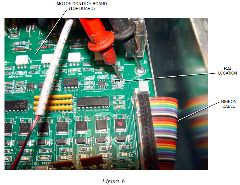
7. Checking for Correct Voltage from the Machine Control Board.
Before taking voltage reading, make sure the ribbon cable to the right of R22 is fully seated into the Motor Control PCB and the Machine Control PCB. Using a voltage meter, select VDC and attach the black wire lead to the Phillips head screw for ground, and the red lead to the top of R22. Refer to Figure 6. This reading should be between 2 to 5 VDC while running the Drive motor in the reverse or forward directions.
If there is no voltage present, or the reading is below -2 or +2 replace the Machine Control PCB, the bottom board inside the electrical enclosure. If the correct voltage is present, replace the Motor Control PCB.
Quick Notes:
A weak signal from the machine controller PCB or motor controller PCB of -2 or +2 the machine will run slow. This signal must be above 2 volts + or – to obtain the proper speed.
Normally, if the drive motor will run one direction or the other this means you have 120 or 230 volts to the regenerative drive PCB.
Revision Date:
03/17/16 - Released to KB
1.2. Brunswick Computer Lane Monitor
1.2.1. Calibration Error - One or more Calibration Strips are Missing or Out of Range
Environment: Computer Lane Monitor
Applicable Version(s): All
Issue:Calibration Error – One or more Calibration Strips are missing or Out of Range:
Solutions/Reasons:
Old or Defective Calibration Strips.
UV Bulb worn and needs replacement.
Component failure, send to Brunswick Electronic Repair Center.
1.2.2. Calibration Strip Tips and Use
Environment: Computer Lane Monitor
Applicable Version(s): All
Description:
The standard calibration option must be used the first time that the Computer Lane Monitor is loaded into your computer. After that, it is recommended that you routinely use the short calibration option since the software program will automatically prompt you when it is necessary to run the standard calibration.
You should record the first date on one of the three calibration strips and use this same strip for short calibration for the first four months. The second strip should be used with the short calibration for the next four months with the third strip being used for the last four months of the year.
The four month suggested life for each calibration strip is based on normal (daily) use of the same strip.
The best accuracy is obtained when the tape samples are read immediately after the reader is calibrated. For this reason, it is recommended to repeat the short calibration every hour while reading tape samples.
Another tip is to use the Optical Reader without the stand while calibrating and reading tapes. This reduces most bright ambient light from entering the “Tape In” slot which may cause errors in accuracy.
1.2.3. CLM 2.0 Software
System:
Computer Lane Monitor
Compatible Computer Models:
Black CLM Unit - Incompatible. Silver CLM Unit - Compatible. Gold CLM Unit - Compatible.
Important:
As of 12/31/2020, Brunswick has discontinued support for the Computer Lane Monitor.
This includes both Technical Support and Electronic Repair options.
There is a limited stock available of parts for the unit, Brunswick Customer Service can assist with any parts request.
*Please make sure to unblock any files prior to extracting/installing.
Failure to do so can cause unexpected behavior, or prevent the system from running properly. Unblocking Files
Revision Date:
12/01/2021 - Updated for missing End of Life reference. 07/28/2017 - Released to KB.
1.2.4. Computer Lane Monitor Software Versions Compatibility
Environment: Computer Lane Monitor
Applicable Version(s): 1.01, 1.02, 2.0
Description: Computer Lane Monitor Software Versions Compatibility
Related Information and Links:
Computer Lane Monitor software version 1.01 & 1.02 part # 61-860273-400 can be used with these Windows operating systems below:
Windows 95
Windows 98
Windows 2000
Computer Lane Monitor Software version 2.0 part # 61-860273-401 can be used with these Windows operating systems below:
Windows XP
Windows Vista
Windows 7
Windows 8
1.2.5. Device Unavailable Message
Title:
Device Unavailable Message
Environment:
Computer Lane Monitor
Applicable Version(s):
1.01, 1.02
Issue:
Computer Lane Monitor will not communicate
Cause:
Communication port is not configured correctly or when operating system has been upgraded.
Solution:
Requires re-configuring of the COM port.
1. Open file C:\Windows\CLMWIN.INI using notepad*. Select the 'All Files' in the File Type pull down.
2. To reset the comm port change the [COMMPORT] section to the following:
[COMMPORT] PORT=NONE
3. Save file
4. Open The Computer Lane Monitor Software. Click “OK” on the Brunswick Lane Monitor window. Click Configure on the File Toolbar. Select Communications and set COMM port to appropriate COMM. (1=Serial Port, 3=USB Port).
*For Windows 2000 PRO follow this path for locating the CLMWIN.INI file: C:\WINNT\CLMWIN.INI
For Windows XP: C:\Windows\Windows\CLMWIN.INI
1.2.6. New "Zero Tape" Procedure
Title:
Computer Lane Monitor New 'Zero Tape' Procedure
Environment:
Lane Maintenance
Applicable Version(s):
1.01, 1.02, 2.0
Description:
New 'Zero Tape' Procedure
Applicable Files:
'Zero Tape.pdf'
1.2.7. No Tape Reader Detected Message
Title:
No Tape Reader Detected
Environment:
Computer Lane Monitor
Applicable Version(s):
All
Issue:
Computer Lane Monitor is not communicating with the computer, Message box says "No Tape Reader Detected".
Cause:
USB adapter not installed or updated with the latest version driver, Unit not connected to computer or cable is defective, UV Bulb is not in fixture, defective UV start switch or USB port not configured properly
Solution:
1. USB driver not updated. Download the latest driver for the Computer Lane Monitor from FTDI, (see attachment CDM Driver 2.08030)
2. Unit not Connected to computer or cable is defective. Plug in cable or replace.
3. UV bulb is not in fixture or burnt out. Remove Computer Lane Monitor from chassis and reinstall bulb. Otherwise, replace bulb part # 61-100060-000.
4. Defective UV start switch. Send Computer Lane Monitor in to Brunswick Electronic Repair Center.
5. USB port not configured properly.
The computer assigns the port when the cord is plugged in.
Newer computers may assign a USB device to comm5 (or higher) which the CLM software cannot find.
To re-assign a USB port:
Click Start, Settings, Control panel, System, … some laptops will have the following path- Start, Settings, Control panel, Performance and maintenance, System…
From the System menu, select Hardware, Device manager.
Go to Ports click on the + sign.
Locate the USB port and note the comm setting. If it is higher than 4, click on it and the properties window will appear. Click on the “port settings” tab. Another window will open and you will see a box labeled Advanced Settings.
Click the box and there will be a place to set the comm port to a number from 1 -4.
Offset potentiometer is not adjusted correctly; Send unit in for repair to the Brunswick Electronic Repair Center 800-937-2695 for details.
Too much equipment running off of one circuit.
If the Empty Tape Slot Reading is above 7: Unit is not sending the data properly to the software. Send unit in for repair to the Brunswick Electronic Repair Center.
Solutions:
- Make sure there is power to the Computer Lane Monitor (CLM).
- Main switch in back is set to the “On” position.
- If you press and hold down the front bulb switch and the amber light should come on, if not the bulb has failed or has come loose on the socket. (See “Replacing the UV Bulb” procedure)
Related Information and Links:
To view the ETSR:
Click Configure and select Advanced Settings.
Click OK on Caution window.
Change the Minimum A/D value to tell U.V. bulb is ON to 0 and click OK. Reader should show UV Bulb ON and proceed with warm-up mode.
Click the Calibration button and the calibration window will display the ETSR.
1.2.9. UV Source Tube Replacement and Tips
Title:
UV Source Tube Replacement and Tips
Environment:
Computer Lane Monitor
Applicable Version(s):
All
Issue:
Lane monitor takes longer to pass the warm up check and does not maintain its calibration as long.
Cause:
UV source tube aging, unstable
Solution:
As the UV source tube ages, the Empty Tape Slot reading will decrease and become less stable. You may notice that it takes longer to pass the warm-up check and that the unit does not maintain its calibration as long. The age of the source tube will also affect the Calculated Calibration Value. You should monitor both the Empty Tape Slot reading and the Calculated Calibration value during the calibration process. When the Empty Tape Slot reading drops below 15 and the Calculated Calibration Value increase above 1.5, it is time to replace the UV source tube, Brunswick part number 61-100061-000. New replacement UV source tubes now require 96 hours of “Burn-in” time.
Previously, the burn-in period was 48 hours, but this has changed due to manufacturing environmental regulations. New UV source will rattle, which is caused by a special pellet that is injected into the source tube and will evaporate during the burn-in period. DO NOT use the GE or Phillips brand UV source tube replacements.
1.2.10. Warm-UP Failed Message
Environment: Computer Lane Monitor
Applicable Version(s): All
Description: How to correct a Warm-up failed message.
Solution:
Warm-Up Failed Message:
UV Bulb is worn and is unable to pass warm-up tests.
Replace UV Bulb
Component failure on circuit board.
Send unit in for repair to the Brunswick Electronic Repair Center.
1.3. Brunswick Envoy
1.3.1. Battery Charger
1.3.1.1. Custom Battery Charger Settings for Lithium Battery
Environment:
Charging System, Lithium Battery
Applicable Version(s):
Envoy Lane Machines with Lithium Batteries
Procedure:Instructions for selecting Custom Battery type and Custom Settings for Lithium Battery Charging.
Important: Please read
instructions completely first as the charger will shut down after 30 seconds
of idle anytime during this process and you will have to restart this
procedure.
Disconnect the
charger from the side charging port of the Envoy lane machine to make this
adjustment and turn on when adjustment is completed.
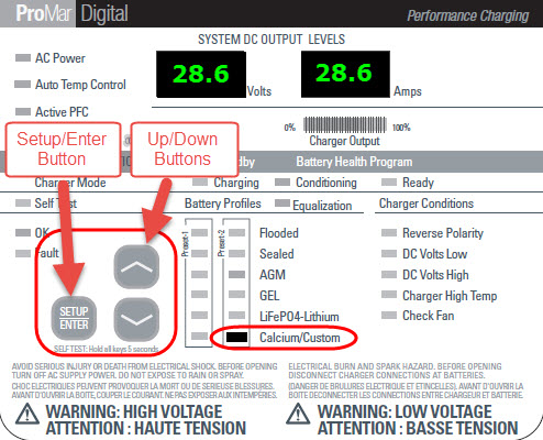
1. Press and hold the Setup/Enter button for 5 seconds. (See Figure #1)
2. The current battery type
and Voltage/Amperage displays will flash.
3. Using the up/down arrows
(See Figure #1) move the selected LED light to Preset #2 Calcium/Custom.
4. Once set to Preset #2 Calcium/Custom both the Volts and Amps and the Charging and Conditioning
LED’s will begin flashing.
5. Press the Setup/Enter button. The display should now show the Volts flashing and the Amps display
blank. Press the up arrow button to move the voltage to 28.6 volts.
6. Press the Setup/Enter button.
The Amps display will flash and the Volts display will be blank, the Ready LED will also be flashing. Press the up arrow button to move the Amps to 28.6
Amps.
7. Press the Setup/Enter button to lock in the settings. Your charger is now ready to
operate.
Figure #1
Note:
During this process, real-time voltage and amperages will not be displayed
until after you press the “Setup/Enter” button in step 7.
Some chargers may have up to a 0.2 volt
difference in the real-time voltage readings.Example, if set for 28.6 the real-time voltage results could be 28.8
volts.
Revision Date:
08/04/2021 - Added details regarding charging process. 06/01/2017 - Released to KB
1.3.2. Envoy Conditioning System
1.3.2.1. Conditioner Pump Head Removal and Replacement - Envoy
Environment:
Envoy Lane Machines Conditioning System
Applicable Version(s):
All Versions with Aquatec Conditioner Pump
Procedure:
Conditioner Pump Head Removal and
Replacement – Envoy
Tools needed:
Allen wench size 1/8”
3/8 Drive ratchet and 3/8” socket
#T-25 Torx screw driver
Card board
Terry cloth towels
Inch pound torque wrench (preferred but not necessary)
1/4” and 3/8” vinyl caps to plug hoses
New pump head 14-100771-051 (Can be used for
conditioning or cleaner pumps)
Instructions:
1. Ensure
that the conditioner tank is no more than 1/3 full. (This first step is
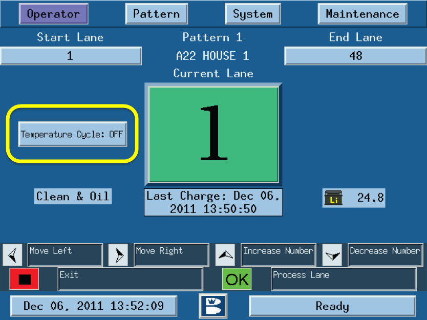
optional to reduce spillage of conditioner)
a. In the GUI navigate to the “Operators Screen”
Highlight the “Temperature Cycle” and turn it to “On”.
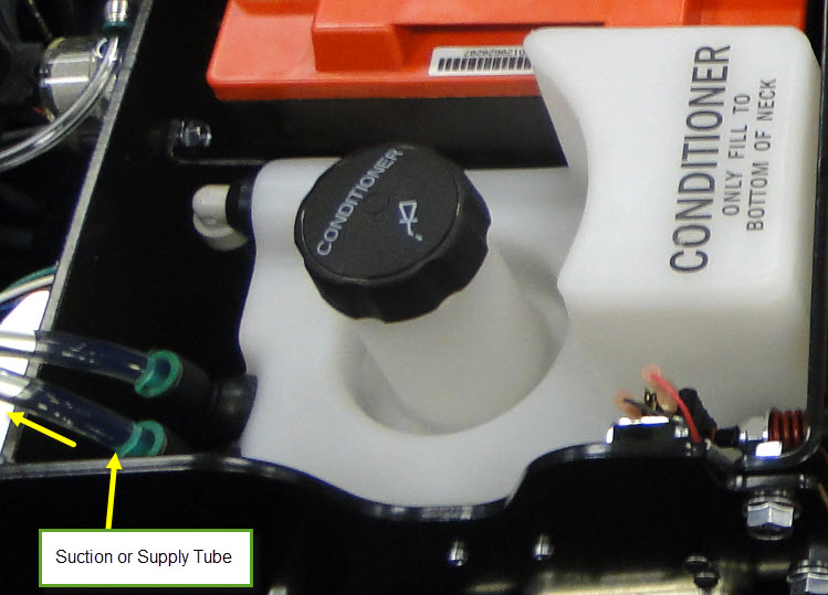
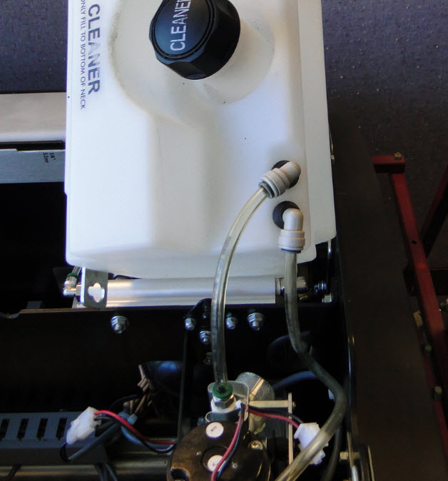
b. While the pump is running, at the tank
connection, disconnect the suction tube that goes to the inlet on the pump. (See
Figure #1)
Figure #1
c. When conditioner stops flowing back to the tank,
turn off temperature cycle. Reconnect the suction tube on tank.
2. Removing the Conditioner Pump Assembly:
a. Disconnect the electrical connections for the
Pressure valve and the Conditioner Pump.
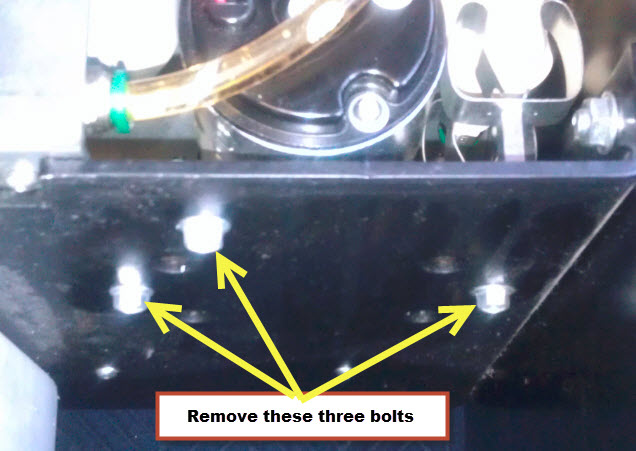
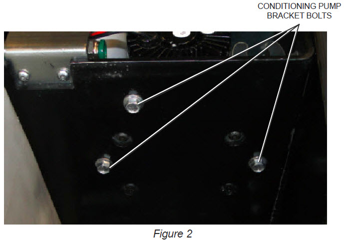
b. Remove the 3 bolts that mount the pump assembly
to the wall. Remove 1/8” Allen cap screw (Figure #2)
attaching the conditioner pump bracket to the frame.
Figure #2
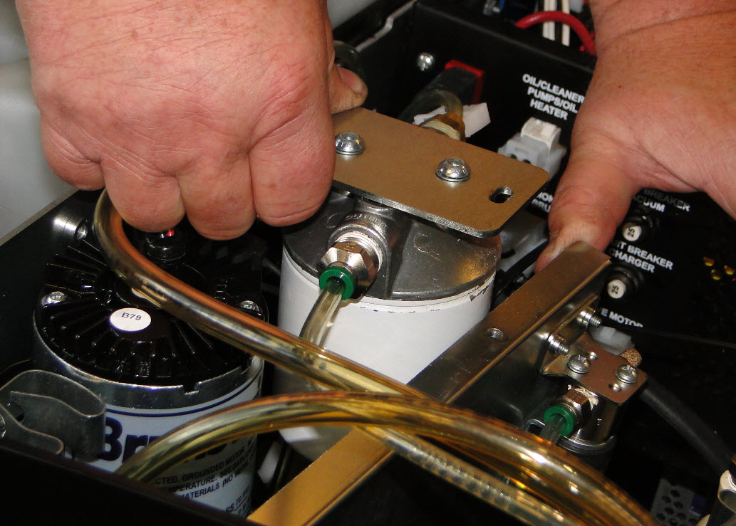
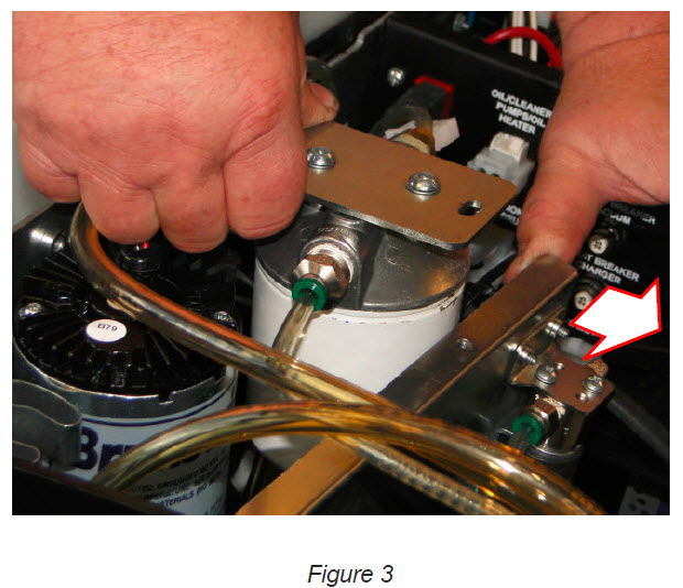
c. Take your hand and hold onto the bracket, use
your other hand to pry the shield away from the oil pump filter assembly
(Figure #3) and at the same time raising the pump assembly up and out.
Figure #3
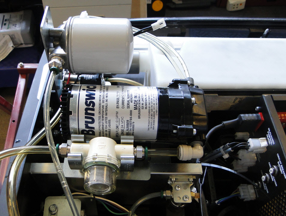
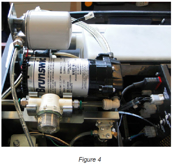
d. Flip entire pump bracket and assembly upside
down so that the 7 bolts that fasten the pump head are accessible (Figure #4).
Note: Lay a piece of card board and terry cloth towel under the oil
pump assembly to catch oil drippings and to use as a support to work on.
Figure #4
e. Disconnect the inlet and outlet fittings/Tubes
from the pump. Use the vinyl caps (if used) to plug the hose ends.
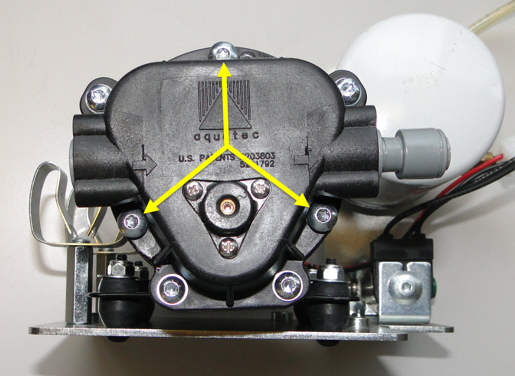
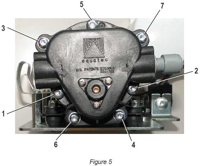
f. Remove the 3 large Torx Head bolts (Figure #5) from
the pump using a T-25 screwdriver. Retain these bolts, Remove the pump head
from the pump motor.
Figure #5
g. Place the new pump head 14-100771-051 on the
pump motor. Align the 3 bolt holes and finger tighten the bolts.
3. Torquing the bolts:
a. Preferred method: using a torque wrench and a T-25
bit, gradually torque the bolts to 27 in-lbs.
b. Then ensure that all 7 bolts are at 27 in-lbs.
Alternate method: Using a manual screwdriver with a T-25
bit, gradually tighten the 3 bolts until they are very tight by hand. Using any
wrench/lever or other mechanical means may over tighten and break the bolts or
damage the pump! Ensure that all 7 bolts are very tight by hand.
Re-attach
the fittings/tubes to the pump.
a. Re-attach the hoses back onto the new pump head. b. Re-attach pump bracket to the frame. c. Re-connect the electrical connections for the
pump and the pressure valve. d. In the GUI navigate to the “Operators Screen”
Highlight the “Temperature Cycle” and press “Okay” to turn on the temperature
cycle. Check for leaks. e. Continue to run temperature cycle until all air
has been removed from the conditioning system.
Revision Date:
12/20/2016 - Released to KB
1.3.2.2. Envoy Conditioner Pump Leaking from the Power Head
Environment:
Envoy Lane Machine
Applicable Version(s):
All
Procedure:
The Envoy conditioner pump head to motor bolts may not be
tight on some conditioner pumps.
New Envoy lane machines and new conditioner pumps shipped between 2/1/2014 and 6/30/2014 may experience seepage of conditioner from the pump head to motor area. This can be fixed by tightening the pump head bolts to factory specifications.
Below are the instructions to remove and replace the conditioner pump and tighten the pump head bolts.
Tools Required:
3/8” Drive ratchet and 3/8” socket, or 3/8” wrench
1/8” Allen wrench
T20 Torx socket
Torque wrench with Inch Pound or Newton Meter scale
Parts Required: None
Procedure: Note: It is not necessary to remove any of the conditioner pump hoses for this procedure.
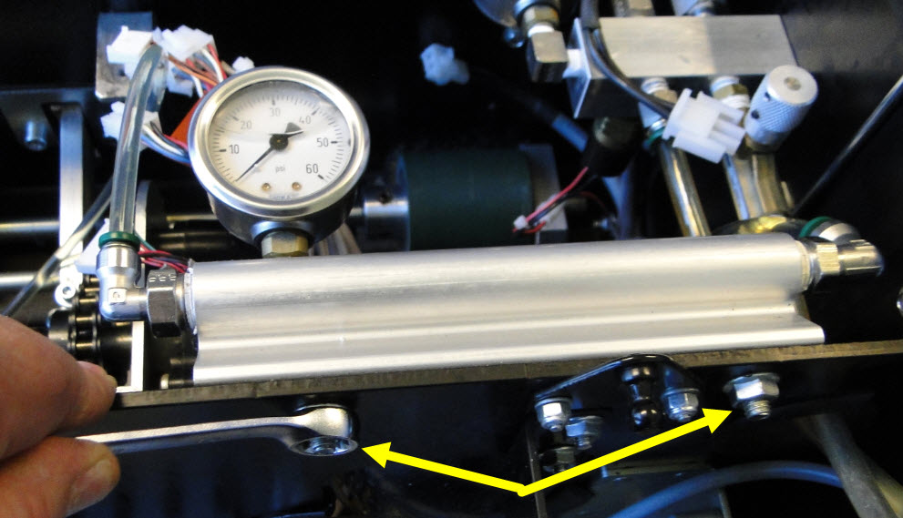
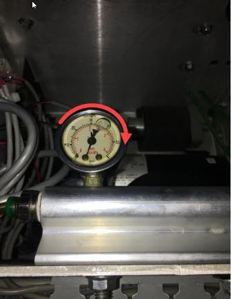
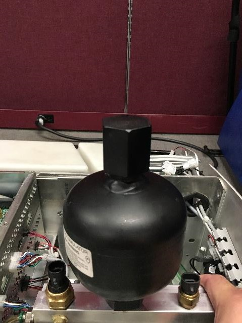
1. Relieve the conditioner pressure using the
lane machine GUI as follows:
Highlight the “Oil Pressure Valve” button and press “Okay” to relieve the oil pressure to zero as shown on the GUI digital gauge.
Check the analog gauge on the accumulator rail to verify zero pressure.
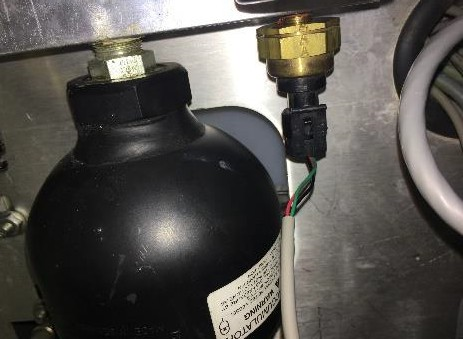
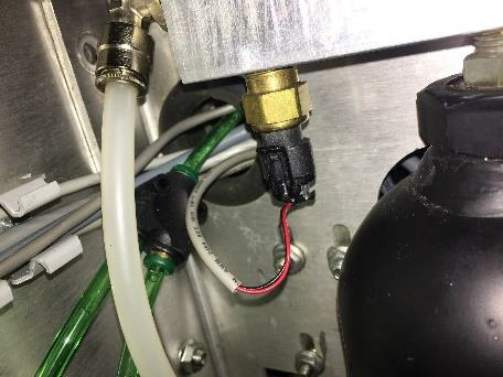
2. Locate and disconnect the
electrical connector for the conditioning pump and the oil pressure valve.
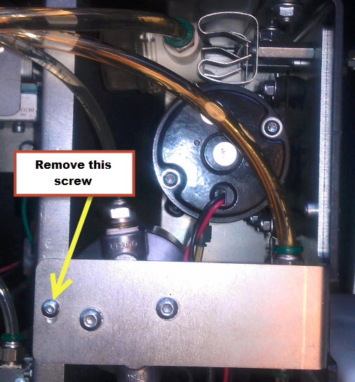
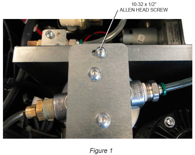
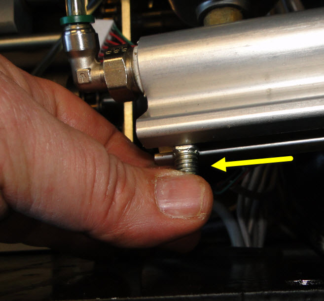
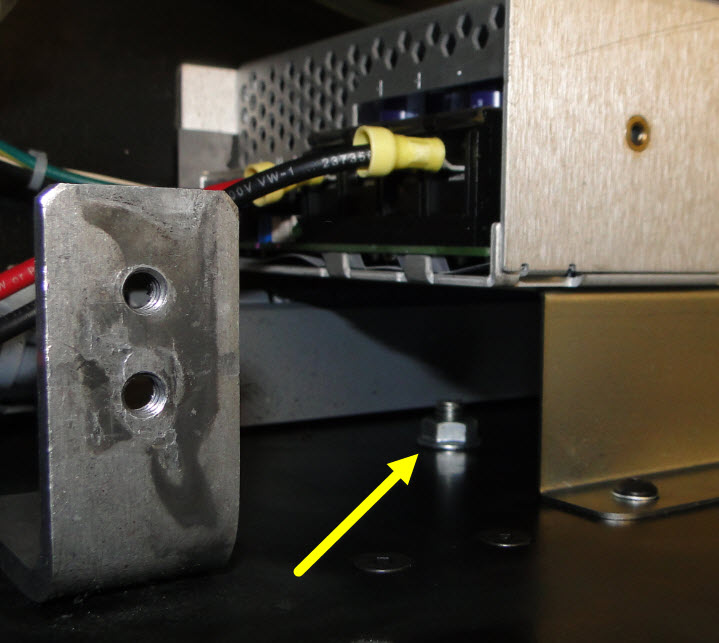
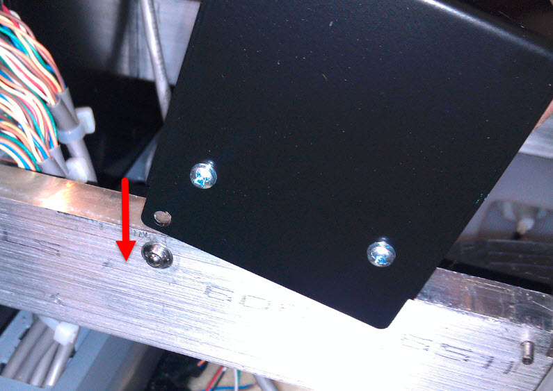
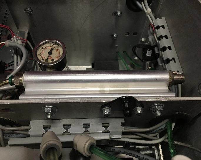
3. Remove the small 10-32 x
1/2” long Allen head screw that secures the cross bracket to the conditioner
pump oil/filter pan. Refer to Figure 1.
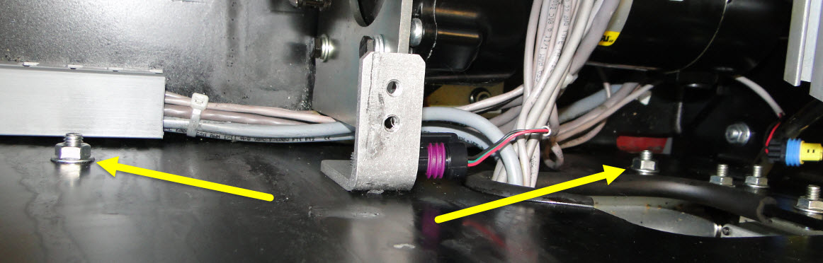
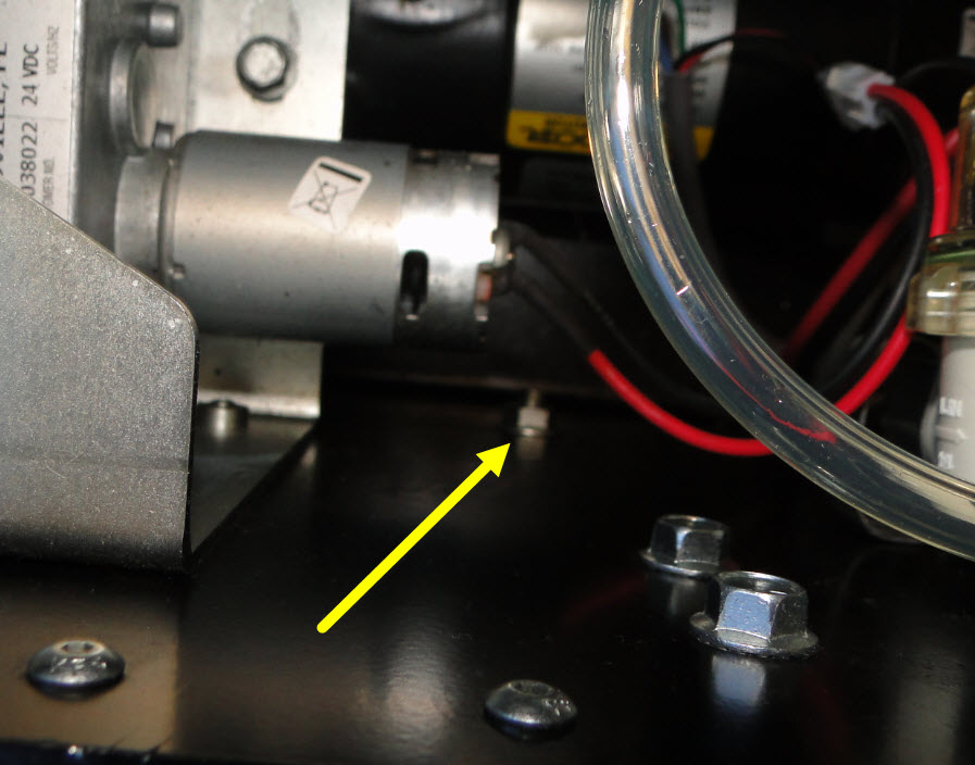
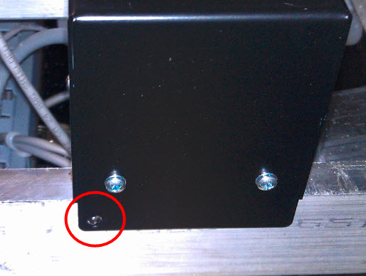
4. Remove the three
conditioning pump bracket bolts located on the outside wall next to the waste
tank. Refer to Figure 2.
5. Push the oil pan wall away
from the bracket so that the complete assembly can be lifted up and out of the
oil pan tray. Refer to Figure 3.
6. Lay the assembly across the dividing wall between the oil pan and center tub section. Refer to Figure 4.
7. Using a torque wrench and T20 Torx socket, tighten the seven screws to 26-28 Inch pounds or 3.1 Newton Meter Nm. Start with one screw and alternate sides of the pump head when torquing the screws. Refer to Figure 5 for torquing sequence.
8. Reverse the pump removal
procedure (step 5 – step 2) to re-install the conditioner pump and bracket
assembly back into the machine.
03/17/16 - Released to KB
1.3.2.3. Envoy Injector Rail / Heater Removal and Replacement
Environment:
Envoy and Authority22 Lane Machines
Applicable Version(s):
All
Procedure:Envoy Injector Rail / Heater Element Removal and Replacement
This procedure will show how to remove and replace the
injector rail along with replacing the heater element. There are times when
lane cleaner or other liquids are introduced into the conditioner tank by
accident and the injectors on the injector rail can become clogged and cannot
be cleared out by the injector blow out procedure.
This procedure should also be followed when replacing the
heater element if it fails. The heater replacement instructions are at the end
of this injector rail replacement instructions.
Tools Needed:
Phillips screwdriver
3/8” Closed/open end wrench
3/8” Socket with 3/8” ratchet
6” to 10” 3/8” extension
Small screwdriver or painted screwdriver
Permanent marker for marking the injector cables
Extension hose from your spare parts kit
Screwdriver big enough to fit into the Cord Kill Stud Assembly to hold it in
place
3/8” and 1/4” plastic caps for hoses
To start we need to de-pressurize and empty all the
conditioner and cleaner from the conditioner and cleaner tanks.
See Section #6 Maintenance & Service See Page # 130 for
De-pressurizing the Conditioning System
See Page # 131 for Draining the Conditioner Supply Tank
See page # 126 for Draining the Cleaner Supply Tank
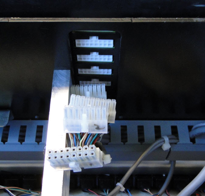
1. Remove the electrical enclosure from the machine.
2. Disconnect all the connections from both RH and
LH side of the electrical enclosure.
3. Remove the GUI, and then remove the
injector cables that are below the GUI screen that route through the center
wall off the machine. Mark these 1-5 so that they can be reinstalled the same
as removed.
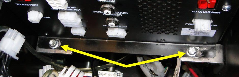
4. Remove the 4 each 3/8” socket head bolts that
mount the electrical enclosure to the 4 “L” brackets.
5. You should be able to now lift the enclosure
straight up and out of the machine and set aside.
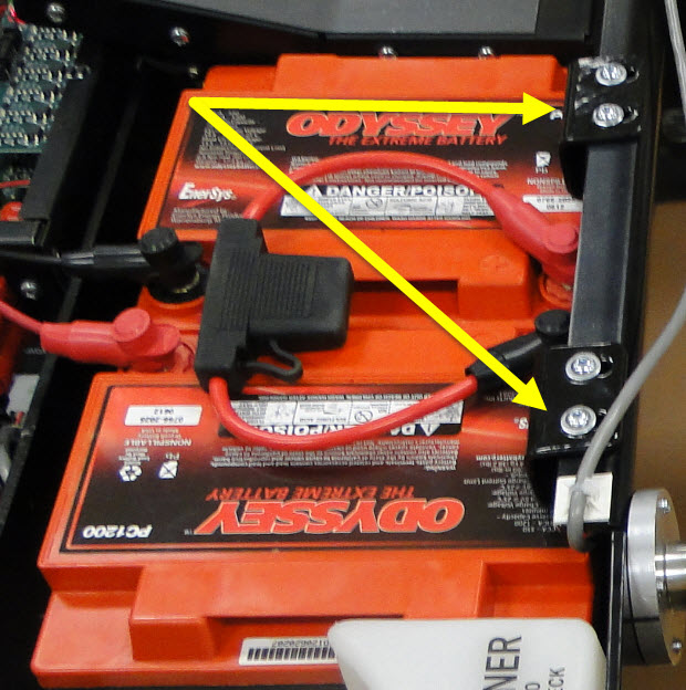
Next, we need to remove the battery and its tray.
6. Remove the two battery clamps.
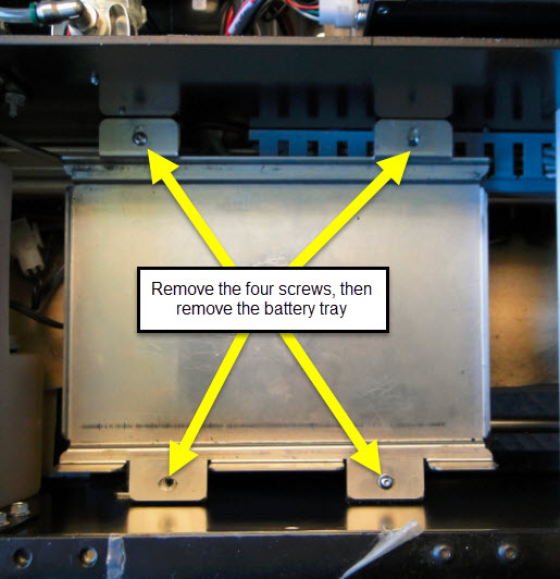
7. Remove the bottom battery tray. There are four
hex cap screws holding securing this plate.
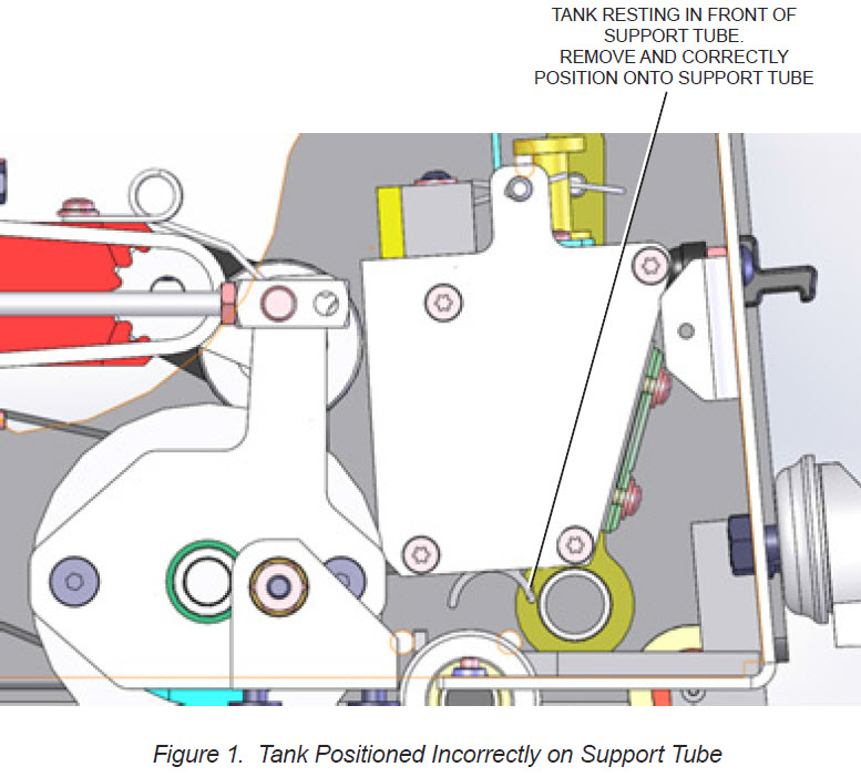
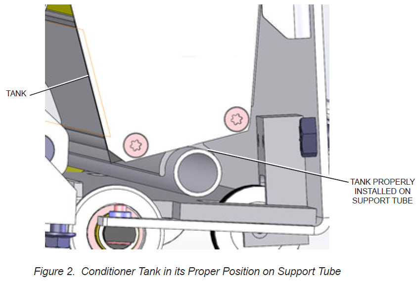
Now, we need to remove the conditioner tank.
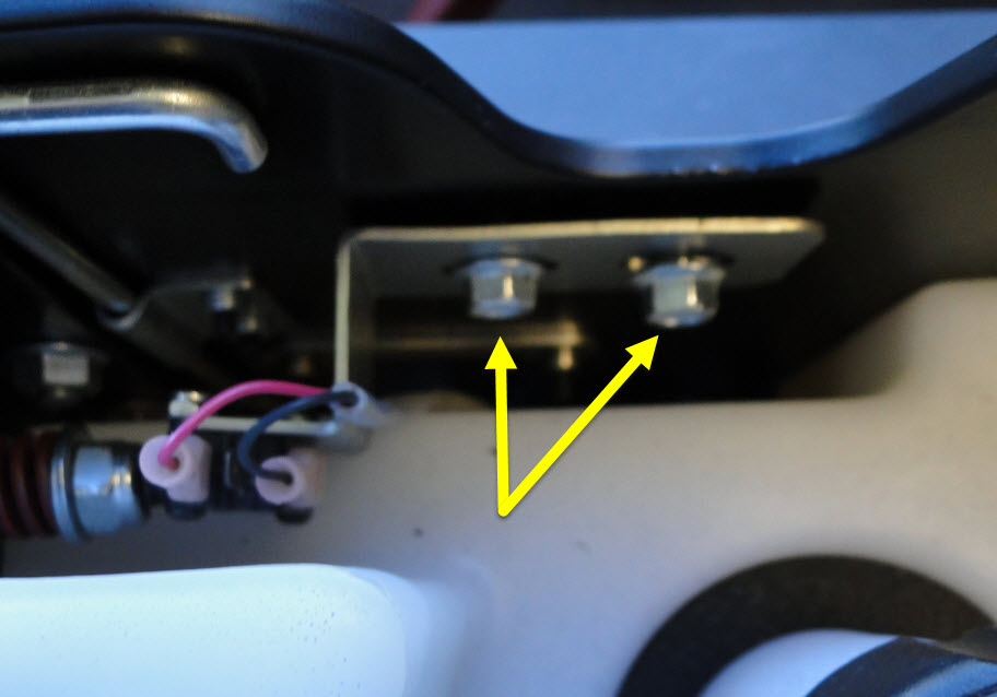
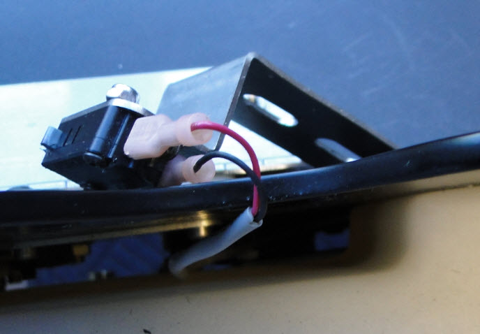
8. Remove the cord kill micro switch bracket by removing the two 3/8” bolts that mount the switch and lay the switch and bracket
over the wall out of the way.
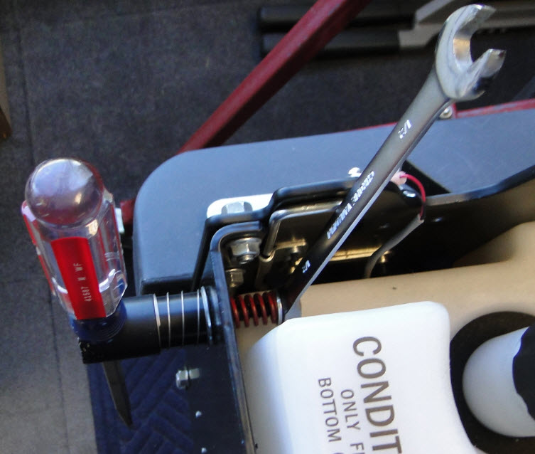
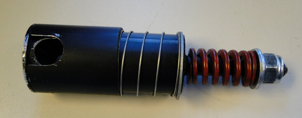
9. Remove the cord kill stud assembly. Use a
large screwdriver to put in the slot where the cord ring would normally go. Then, using a 3/8” closed/open end wrench, start unscrewing the cord kill stud
assembly and remove with the washers and spring. Place all parts back together.
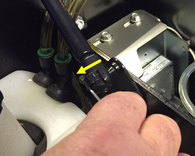
10. Remove the gas spring shock at this location, take a small pocket screw driver and push the clip outwards to unsnap the shock from the ball.
Note: Remember to de-pressurize the conditioning system and
drain the system before you remove the hoses!
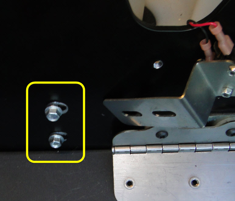
11. Find the two conditioner tank mounting bolts on
the side of the machine and remove these. You will need to remove the side cover.
12. The tank is now loose and can be lifted straight
up, but be careful of the air vent fitting towards the front of the machine. You
can maneuver that fitting around the nut and ball joint of the hood spring.
Just take your time.
13. Unplug the connection to the level sensor.
14. Lay the tank over to the side, or remove
the tank by removing the two 3/8” hoses from the tank making sure you note
where they came from. Then, take the 3/8” caps and cap off the both hoses so
there are no leaks.
15. Remove the ¼” vent valve hose and cap.
Next, we need to remove the cleaner tank.
16. Remove the two 3/8” socket head screws that mount the cleaner tank to the back wall.
17. Slowly lift the tank up and disconnect the level sensor connection.
18. Lay the tank over the side,or remove the tank by removing the two 3/8” tubes from the fittings and cap them off with 3/8” caps. Remember to drain the system and tank if you are removing the tank.
Before we remove the injector rail we will need to remove
the injector connections from the injectors themselves.
19. Use a small pocket screwdriver or a paint can
opener like in the tools picture, move the screwdriver between the injector and
the felt padding centering the screwdriver to the injector.
Then, push up on the screwdriver, this will push
up on the clip on the injector unlocking it. While the injector is unlocked,
grasp the connection and pull away from the body of the injector.
20. You will need to do this to all 39 injectors.
21. After you finish unplugging all 39 connections,
disconnect the heater connection on the LH side of the injector rail under
where the conditioner tank was mounted.
To get at the rail mounting nuts under the accumulator rail,
you will need to remove the accumulator.
22. Remove the two mounting nuts and lift and move the
accumulator away from the wall. Slide the two carriage bolts out and set aside
as they may fall out and get lost.
23. You should now have clearance to remove the two nuts
for the injector rail.
24. Remove the two other nuts along the rail on the
inside so that the rail is loose. These are located below the buffer up/down
motor and below the AC power converter.
Removing the rail:
25. Now that the rail is loose, you can disconnect
the 1/4” or 3/8” hose that leads up to the spin on oil filter from the end of
the injector rail on the left-hand side and remove the other 3/8” hose on
the right-hand side that leads up to the accumulator rail.
26. Drop the injector rail out the
bottom of the machine.
Once you have the old injector rail out you can now install
the new rail by following these instructions in reverse.
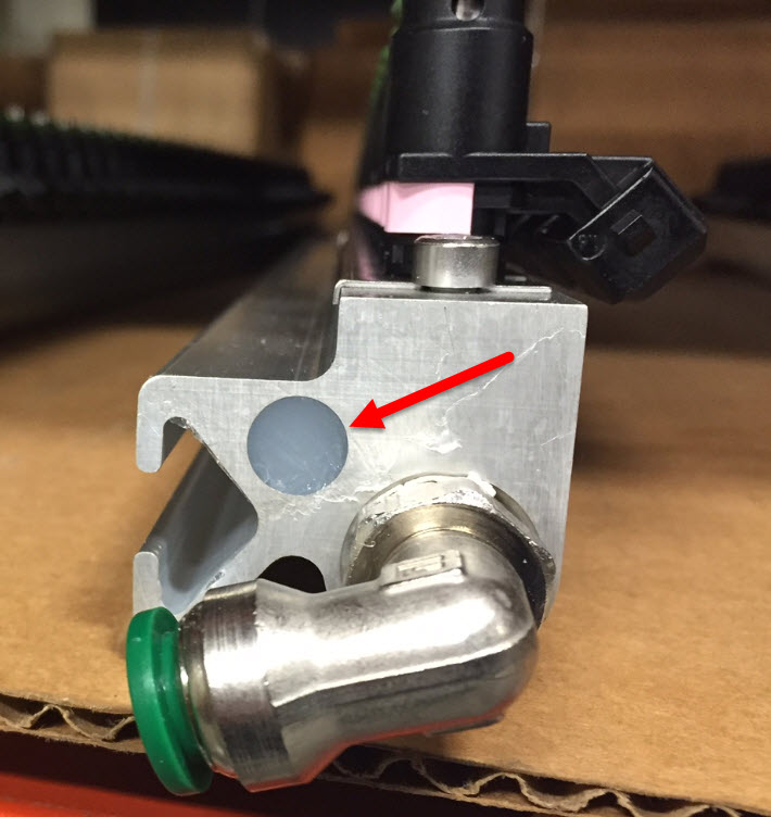
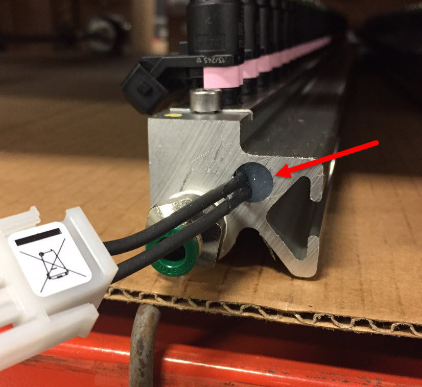
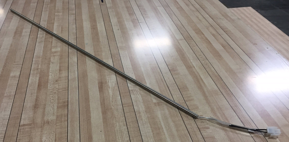
Replacing the heater element in the
injector rail:
By following the above replacement instructions, you will
have the injector rail out of the machine. Now, you can work on this injector
rail on the bench to replace the heating element.
27. Remove all the silicone
from each end of the rail that holds the element into the rail.
28. Pull out the heater
element from the rail. If it does not want to come out easily, you may have to
take a 1/4” threaded rod 20’ to 24” long to tap the element out of the injector
rail.
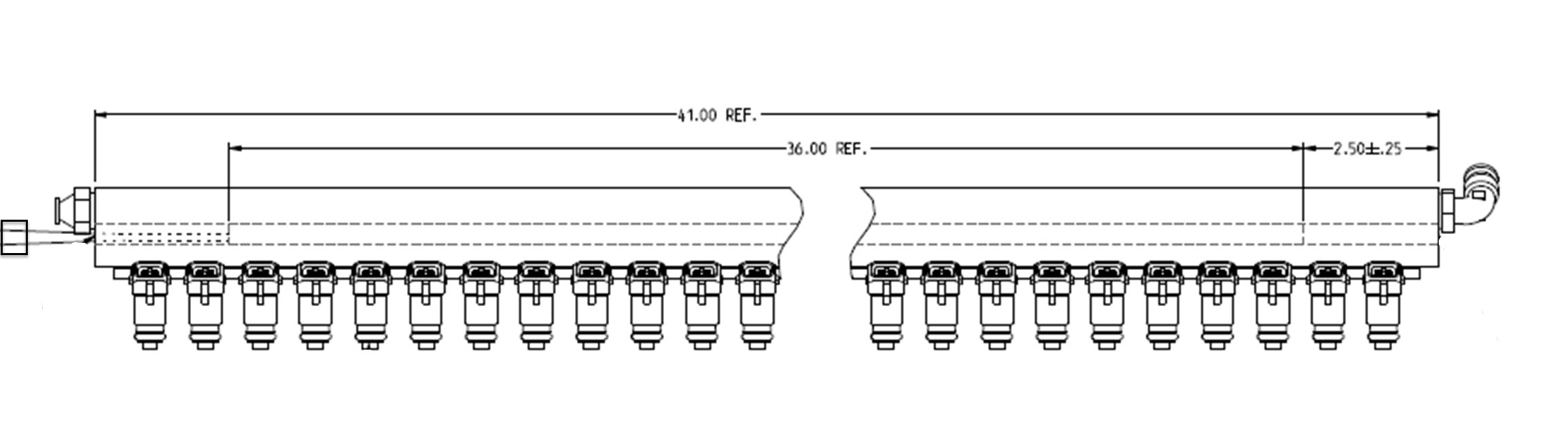
29. Once the heating element is out of the injector
rail, install the new element into the rail trying to center it inside the rail.
It should be placed 2-1/2” from each end. The rail is 41” long and the heating
element is 36” long. Center it the best you can and then fill the cavity
back up with silicone on both ends.
30. Reinstall the injector rail in reverse from the
instructions above.
Applicable Files:
Related Information and Links:
Revision Date:
11/22/2016 - Released to KB
1.3.2.4. Matching Address of Replacement Transmitter w/Existing Remote Stop Receiver
Environment:
Lane conditioner machines
Applicable Version(s):
Envoy and Max lane conditioner machines
Procedure:
This procedure explains how to match the address of a replacement 14-100907-001 transmitter with existing remote stop receiver.
Applicable Files:
'14-100907-002rNC.pdf'
Related Information and Links:
Revision Date:
09/02/2022 - Released to KB
1.3.2.5. Max and Envoy Lane Machine Heater Troubleshooting Instructions
Environment:
Max or Envoy lane machine
Applicable Version(s):
All
Procedure:
See attachment
Applicable Files:
'Max and Envoy Lane Machine Heater Troubleshooting Instructions.pdf'
Related Information and Links:
Revision Date:
03/05/2020 - Released to KB
1.3.2.6. Process for Resolving Inconsistent Injections or Purging Contamination from the Conditioning System
Environment:
Envoy and Authority22 Lane Machines
Applicable Version(s):
All
Procedure:
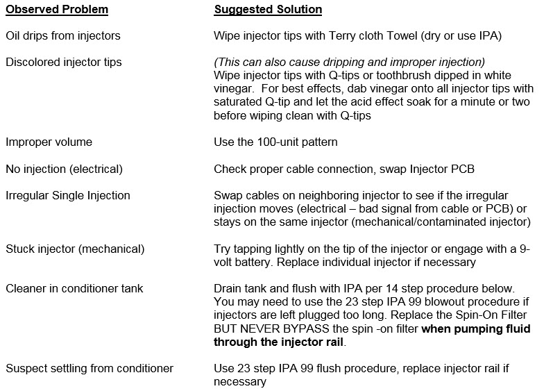
PROCESS for RESOLVING INCONSISTENT INJECTIONS or PURGING CONTAMINATION
from the Conditioning System
Note:Before
starting on the following 12 or 23 step procedures, please read these
“Suggestive Steps to Solve Inconsistent Injections”. Try these first, and if issues persist, go to
“Purging Contamination from the Conditioning System” below.
Suggestive Steps to Solve Inconsistent Injections:
Purging Contamination from the Conditioning System:
Refer to pages 132-144 of the Envoy Operation & Service Manual
(14-900101-000)
IF CLEANER IS ACCIDENTALLY ADDED TO THE CONDITIONER TANK BUT NOT CIRCULATED THROUGH THE SYSTEM:
DO NOT OPERATE THE MACHINE BEFORE CONDUCTING THE 14 STEP PROCEDURE below to
contain the resulting white sludge from being spread through the rest of the
conditioner system.Conducting this
procedure as soon as possible after the cleaner has been added to the
conditioner tank will minimize the negative effects and avoid the need to
conduct the 24-step process to purge the contamination from the complete
conditioner system.
Remove the pump outlet tubing at the compression
fitting where it connects to the inlet of the Spin-On Oil Filter.
Use union fitting to attach ~40” tubing (from spare
parts kit or local hardware or plumbing store).
Place loose end of this tube into a 2-5 liter
container to collect the waste fluid.
Go to the Diagnostics menu to activate the
conditioner pump to pump all the fluid out of the conditioner tank.
Remove
conditioner tank to remove any solid or gel that remains in the
bottom of the tank. Use IPA99 if necessary to help remove any contamination from inside the conditioner tank before reinstalling.
Fill the conditioner tank with 99% Isopropyl Alcohol
(61-860254-000/61-860254255-000 IPA 99) and purge any remaining
conditioner/cleaner from the system tubing by activating the conditioner pump
until the drain tubing in the waste container runs with CLEAR IPA 99.
Clean or replace the conditioner screen filter. (page
137-138)
Drain the Conditioning Supply Tank completely of all
IPA 99. (pages 133-134)
Fill the conditioner tank with the desired new
Conditioner.
Purge any remaining IPA 99 from the system tubing by
activating the conditioner pump until the drain tubing in the waste container
runs with CLEAR new Conditioner.
Remove the drain tube and reconnect the tube onto
the compression fitting where it connects to the inlet of the Spin-On Oil
Filter.
Replace the 11-655029-001 Spin-On Filter if necessary (pages 135-136). NEVER BYPASS the Spin-On Oil Filter when pumping fluid through the injector rail.
With the machine in the operating position, turn on
the heat cycle to circulate the new Conditioner in the system for a few minutes
to purge air out of the system.
Run the new Conditioner through the injectors by
running a minimum of 5 lanes with the 100 Unit pattern for all 39 injectors for a single zone of 50 feet.
If the above procedure was not effective or if you are unsure if you
contained the cleaner in the conditioning tank before it was spread to the rest
of the system, you will need to conduct the 23-step procedure below:
IF CLEANER WAS CIRCULATED THROUGH THE SYSTEM or if the injectors are suspected of contamination USE THE BELOW PROCEDURE.
Please purchase 2 each 11-655029-001 Spin-On Filters for Replacement During this Procedure.
Completely Drain the old conditioner and residue
from the Conditioning Supply Tank (pages 133-134). Pump out as much of the existing conditioner from the tank and system
tubing as possible (+Physically remove conditioner tank to empty liquid or
contamination below the inner tubing level.) BEFORE adding any IPA99. If the 11-655029-001 Spin-On Oil Filter is completely plugged and blocking the outlet of the pump, it may be necessary to replace it with a new filter at this time instead of at step #7 (pages 135-136). NEVER BYPASS the Spin-On Oil Filter when pumping fluid through the injector rail.
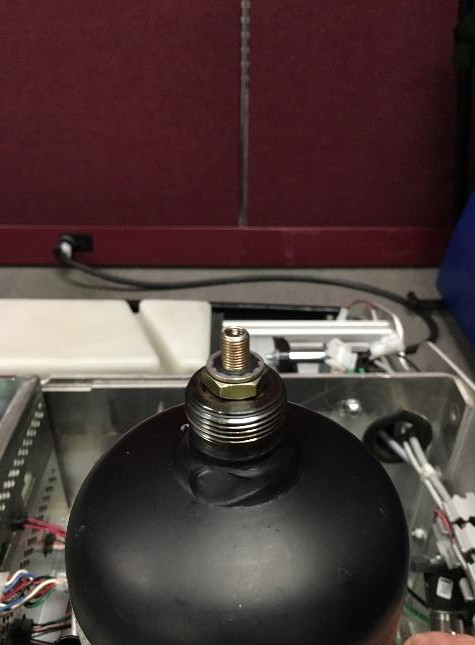
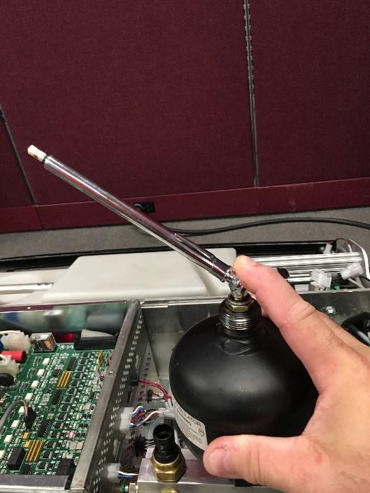
Remove the accumulator from the accumulator rail and drain contents. Pour IPA 99 into the opening and fill to top. Shake the IPA 99 inside the accumulator to wash out any contaminates. Note: When replacing the accumulator, be sure to add Teflon tape to the threads of the fitting before reinstalling the accumulator.
Fill the conditioner tank with 99% Isopropyl Alcohol (61-860254-000/61-860255-000 IPA 99).
Purge any remaining conditioner from the system tubing by activating the
conditioner pump until the drain tubing in the waste container runs with CLEAR
IPA 99.
Remove the drain tube and reconnect the tube from the accumulator rail to the pressure control valve.
Activate the conditioner pump to let the conditioner pressure increase to
45psi in the Diagnostics with the Oil Pressure Valve closed and then quickly
turn the conditioner pump off.Then open
the Oil Pressure Valve to let the pressure drop to 0psi.(This
step helps purge residual conditioner that may be trapped in the accumulator).
Replace Spin-On filter with new one.
With the machine in the operating position, circulate the IPA 99 in the system for a few minutes to purge air out of the system (page 137).
Remove the buffer brush (pages 143-144
Create a special pattern that is 100 units of oil for all 39 injectors
for a single zone of 50 feet.
Run the IPA99 through the injectors by running a minimum of 10 lanes with
this pattern.
Drain the Conditioning Supply Tank (pages 133-134) by pumping out as much
of the existing IPA99 from the tank and system tubing as possible.
Fill the conditioner tank with the desired new conditioner.
Purge any remaining IPA 99 from
the system tubing by activating the conditioner pump until the drain tubing in
the waste container runs with CLEAR new conditioner.
Remove the drain tube and reconnect the tube from the accumulator rail to
the pressure control valve.
Activate the conditioner pump to let the conditioner pressure increase to
45psi in the Diagnostics with the Oil Pressure Valve closed and then quickly
turn the conditioner pump off.Then open
the Oil Pressure Valve to let the pressure drop to 0psi.(This
step helps purge residual IPA 99 that
may be trapped in the accumulator).
Replace the Spin-on
Filter: Remove the spin-on filter that has residual
conditioner and replace it with a new spin-on filter.
With the machine in the operating position, turn on the heat cycle to
circulate the new conditioner in the system for a few minutes to purge air out
of the system.
Run the new Conditioner through the injectors by running a minimum of 5
lanes with the 100 Unit pattern for all 39 injectors for a single zone of 50 feet.
Run the Oil Injector Zig-Zag
Test (pages 91-92) to assure that all injectors are properly firing with the
expected pentagon shaped pattern.
Reinstall the buffer brush. (pages 143-144)
Select an actual pattern and run 10 lanes.
Use the Computer Lane Monitor to assure that the oil
volume is correct for the selected pattern.
If these steps do not clear the injectors, please contact Brunswick Tech Support for additional information techsupport@brunswickbowling.com or Domestic 231-725-4966 or International 231-725-4966
Revision Date:
12/05/2016 - Released to KB
1.3.3. Envoy Electronics
1.3.3.1. Adjusting the DECEL Trim Pot on the Envoy Speed Control PCB
Posted ValuesPosted Values
Environment:
Envoy Lane Machine
Applicable Version(s):
All
Procedure:
Making this
adjustment for the DECEL trim pot will give you more flexibility when making
the Base and End of Lane Speed adjustments. This helps stop the machine faster
in the pin deck area instead of the machine coasting to a stop.
Note: This adjustment is not
necessary for machines built after 1/1/2014
Tools
Needed:
Phillips
Head Screw Driver for removing the enclosure cover.
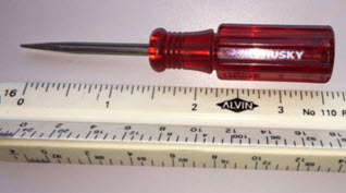
Small Pocket Screw Driver for making the adjustment. (picture below)
1. Remove
the battery cable from the electrical enclosure marked “To Battery”; this will
ensure there is no chance to cause a short.
2. Remove
the top cover on the electrical box using the Phillips screw driver to gain
access to the speed control board.
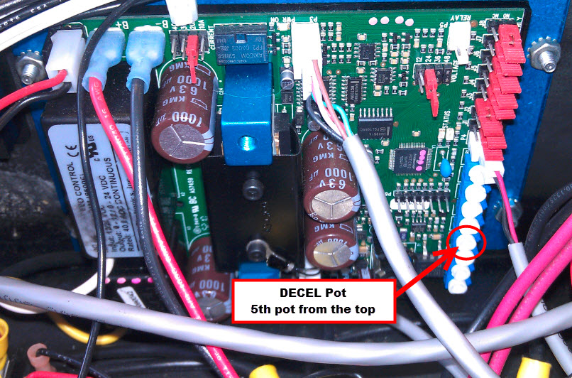
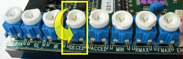
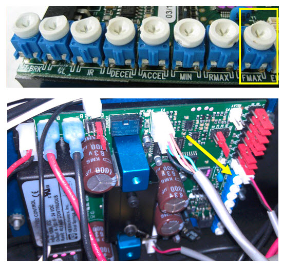
3. The DECEL
trim pot is the 5th trim pot from the top. It will say “DECEL” next
to it. Using a small pocket screw driver adjust the trim pot all the way CCW
until it stops. Do not force the trim pot, but just turn the pot CCW until it
stops.
4. Replace the
cover and make your adjustments in the GUI for the Base or End of Lane Speed
now.
03/11/16 - Released to KB
1.3.3.2. Balancing the End of Lane Speed Adjustment
Environment:
Envoy Lane Machine
Applicable Version(s):
All
Procedure:
Notes to read before continuing:
A
new adjustment to the Decel Trim pot went into effect approximately 1/1/2014 this
adjustment would cause the machine to brake harder at the end of the pindeck
and at the foul line. Because of this we can add higher Base Speed and End Of
Lane voltage adjustments making sure the machine passes through the pin deck
area without it going too far and falling onto the skids at the end of the pin
deck. In testing, after this Decel adjustment was made, we can raise the Base
to its fullest 27 VDC and the End Of Lane Speed to its fullest +15 and the
machine will not run off the end of the pindeck onto the machines skids. It is
suggested that if the “Decel Trim Pot” and the “FMAX Trim Pot” are set
properly, the setting for the End of Lane Adjustment should be set at +6. Then, the Base Speed Adjustment is all that is needed to dial in the correct speed of
the machine.
The purpose if adjusting the Decel Trim
pot full CCW is to apply the brakes stronger at the pindeck end of the
lane.If the mechanic can verify that
the machine already stops very quickly (and has never run off the end of the
lane), then they could skip this step.
The purpose of adjusting the Base
Voltage for Speed Calculations is to increase or decrease the speeds at all
locations on the lane.This is mainly
done if the machine doesn't run the entire lane in the expected time range.
The EOL speed adjustment only affects
the speed in the last ~12" of forward travel at the pindeck end of the
lane.It should always be done AFTER any
Base Voltage adjustments.
End Of Lane Speed Adjustment:
Tools needed: AC Power Cord for
the lane machine
Note: This adjustment is made with the
machine switched over to AC Power, Unplug the battery cable from the port
marked “Battery” on the electrical enclosure and change over the power type
connector to the “AC Power” connection.
The End of Lane Speed Adjustment
is balanced between the upper and lower limits for the center to reduce the
risk of an unknown “borderline” adjustment.
Balancing this adjustment is also
critical to make sure the machine will run successfully if the center ever
needs to use the e RUN feature (without GUI voltage adjustments).
1. Finding the Upper and Lower Limits for the End
of Lane Speed number.
Record the starting End of Lane Speed
Adjustment value.
Reduce the End of Lane Speed Adjustment
in steps of 2 units until the machine stalls in the pin deck area (rear cover
<2” past 2-3 pin spots). Note this number (usually a value of -5 to -15).
2. Set the End of Lane Speed Adjustment
back to the starting value and continue to increase in steps of 2 until the
machine drops off the end of the pin deck. Note: This number also (usually a
value of +5 to +15).It is normal to
have a 20 point spread between upper and lower limits.
3. Set the final End of Lane Speed Adjustment
value halfway between the upper and lower limits that were found above.
Example: If the lower limit
was -8 and the upper limit was +12, then set the final value to +2.
It is best to balance the End
of Lane Speed Adjustment value with a fully charged battery and then
continue to run the machine for the remaining lanes of the entire center to
assure that it runs perfectly through all pin decks without any issues.
If you notice any lane that the lane machine is at risk of stalling or running past the end of the pin deck, make slight adjustments to this
balanced End of Lane Speed Adjustment value.Contact
Brunswick Technical Support if you experience a smaller range between upper and lower limits or
experience inconsistent results with these adjustments.
Revision Date:
3/19/2016 - Released to KB
1.3.3.2.1. Envoy Traction Motor Voltage Adjustment
Environment:
Envoy Lane Machine
Applicable Version(s):
All
Procedure:
This
adjustment is made when you have adjusted your Envoy Base Speed Adjustment to
its high limit of 27 volts and the machines time is still too slow for proper
operation in the selected cleaning mode you are using for that pattern. To time
your Envoy, start the timing once you have put the Envoy onto the lane and you
have pressed the Okay button to send the Envoy down the lane. Once the Envoy
has returned to the foul line and stopped is when you stop the timer.
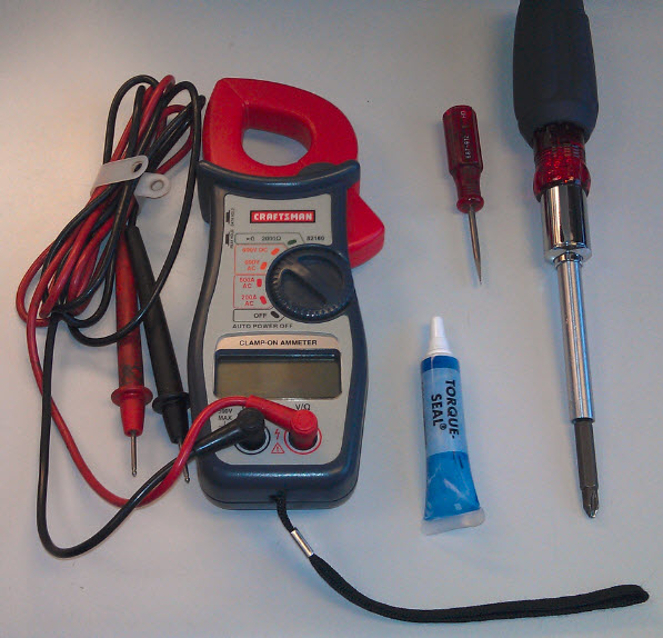
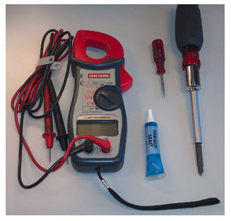
Tools
Needed:
#2
Phillips screwdriver
Small
pocket screwdriver.
Voltmeter
Sealer
or White-Out to lock trim pot into position
Note: Please
run 6-8 lanes before timing the Envoy to warm up the drive motor and to wet
down the absorbent wiper.
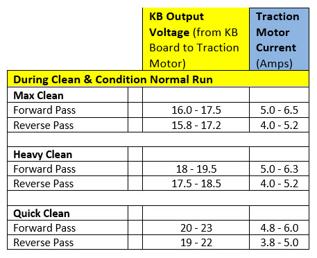
Below are the time parameters for
each cleaning mode.
62-72
Seconds Quick Clean 70-80
Seconds Heavy Clean 80-88
Seconds Max Clean
Normally, the
voltage is factory preset at 14.2VDC. There may be situations where this
voltage may need to be checked, readjusted or raised between 14.2 and 14.8 VDC for
the Envoy to perform at its rated speed for that cleaning mode. The most common
situation is when the Envoy stops in the pin deck area or the machine is
running very slow.
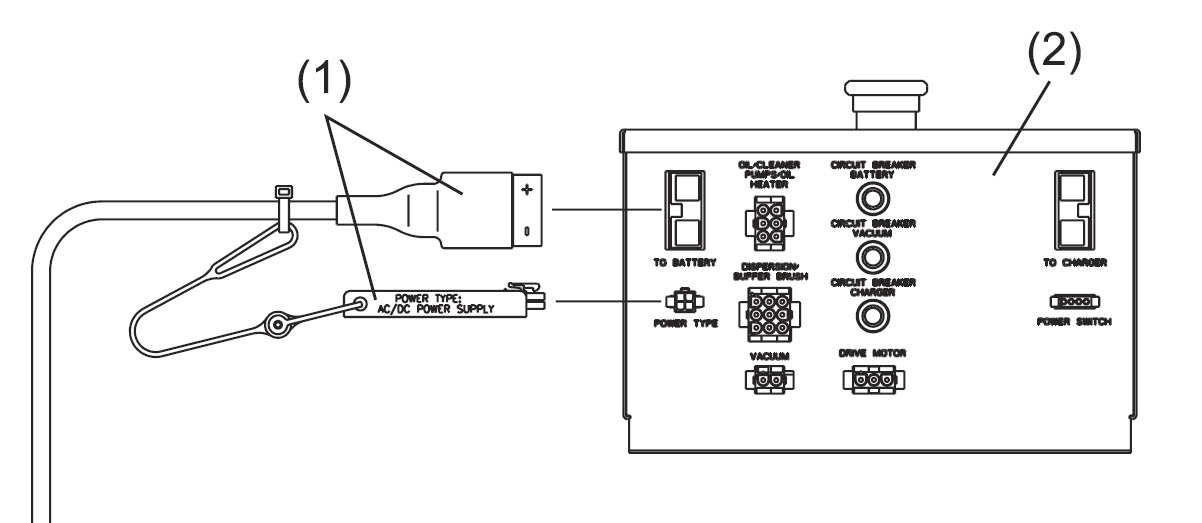
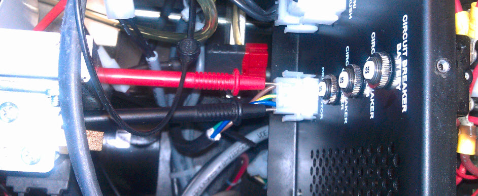
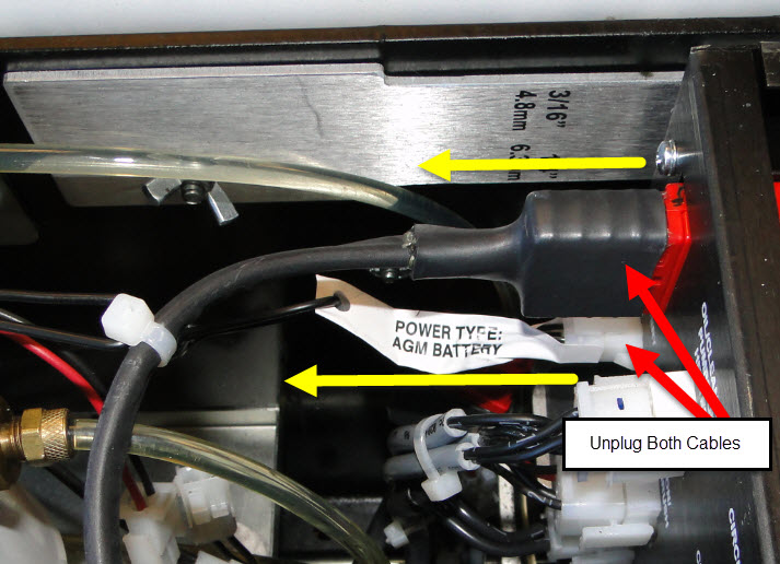
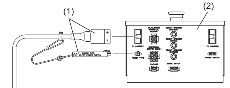
Note: This adjustment is made with the AC power cord. You must change
the power type jumper to AC power to make this adjustment. To switch to
using the AC/DC power supply, first disconnect the AGM or Lithium battery power cable and power
type jumper (#1) from the electrical enclosure (#2). Then, locate the AC/DC power supply red 24DVC power
cable connector (usually coiled just under the left side of the electrical enclosure). Connect the AC/DC power supply cable and power
type jumper to the electrical enclosure. (See Figure #1)
Figure #1
Once you have made the change to AC power, and have ran 6-8
lanes in a clean and condition mode, remove the top cover of the electrical
enclosure by removing the six screws on the top of the enclosure.
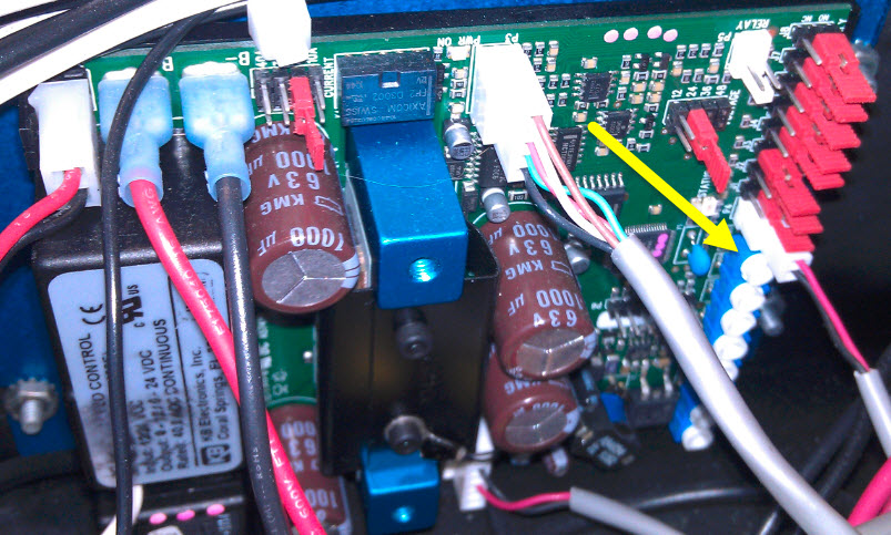
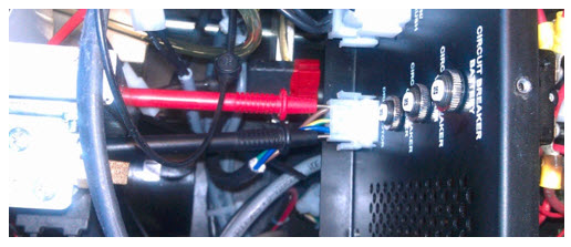
1. Locate the Drive Motor connector on the same side
(left side looking from handle) of the enclosure as the AC power plug was
installed. Leave the drive motor connector plugged into the enclosure. Take
your volt meter leads and put the red lead into the connector wire for the
brown wire, and the black lead into the blue wire on the connector like the
illustration below (Figure #2). Select on your volt meter DC Voltage for this
test.
Figure #2
2. Using the GUI, navigate to Maintenance > Diagnostics > Drive, then make sure the Forward is selected on the right-hand button
display. Now select and press Drive on the left-hand button. This should
start the drive motor and the volt meter should read DC voltage at 14.2 volts.
If not, this voltage will need to be adjusted up to the 14.2 to 14.8VDC.
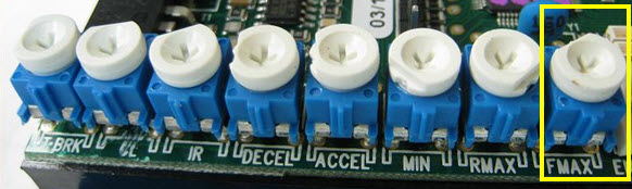
To adjust this voltage higher you must adjust the speed
control boards “FMAX” trim pot. This is the first trim pot from the top of the
board (see Figure #3)
3. While the machine is running in the drive test mode, adjust
this trim pot to 14.5VDC to 14.8VDC. Once this has been obtained, go back to
your base speed adjustment and start at the default voltage of 24.0 volts and
adjust voltage for speed from there.
Be sure to seal the trim pot with a sealer from an electronics shop or use White-Out correction liquid from an office supply store
to seal the trim pot otherwise the adjustment may change from normal everyday
transportation.
Figure #3
Again, below are the
parameters for each cleaning mode.
62-72 Seconds Quick Clean 70-80 Seconds Heavy Clean 80-88 Seconds Max Clean
Note: Please make
sure you run 6 to 8 lanes to warm up the lane machine drive motor and wet the
absorbent wiper so that you can get a more accurate time measurement.
Revision Date:
3/19/16 - Released to KB
1.3.3.3. Envoy Base Voltage Adjustment
Environment:
Envoy Lane Machine
Applicable Version(s):
All
Procedure:
Notes to read before continuing:
A
new adjustment to the Decal Trim pot went into effect approximately 1/1/2014. This
adjustment would cause the machine to brake harder at the end of the pindeck
and at the foul line. Because of this, we can add higher Base Speed and End Of
Lane voltage adjustments making sure the machine passes through the pin deck
area without it going too far and falling onto the skids at the end of the pin
deck. In testing, after this Decal adjustment was made, we can raise the Base
to its fullest 27 VDC and the End Of Lane Speed to its fullest +15 and the
machine will not run off the end of the pindeck onto the machines skids.
The purpose if adjusting the Decal Trim pot full CCW is to apply the brakes stronger at the pindeck end of the lane.If the mechanic can verify that the machine already stops very quickly (and has never run off the end of the lane) then they could skip this step.
The purpose of adjusting the Base Voltage for Speed Calculations is to increase or decrease the speeds at all locations on the lane.This is mainly done if the machine doesn't run the entire lane in the expected time range.
The EOL speed adjustment only affects the speed in the last ~12" of forward travel at the pindeck end of the lane.It should always be done AFTER any Base Voltage adjustments.
Base Voltage Adjustment
Tools
Needed: AC Power cord for the lane machine
The total time of the Envoy to run a
lane is the BEST
indicator of whether or not you need to adjust the “Base Voltage for Speed Calculation”.
This adjustment is made with the
machine switched over to AC Power. Unplug the battery cable from the port
marked “Battery” on the electrical enclosure and change over the power type
connector to the “AC Power” connection.
Don’t bother
to measure the time to run the first lane since it will be inaccurate due to
the following reasons:
The battery voltage may be abnormally high if it was just removed from the charger (the GUI makes the proper speed adjustments based on the loaded voltage at the end of running lane 1).
The squeegee absorbent wiper may have more friction from being dryer on the first lane.
It is best to average the time to run the next two lanes after the system is more stable.
This will also reduce the variation from topography or other variables between any two lanes.
Complete at least 6 lanes before timing the Envoy.
The total
speed of the machine, from pressing the start button to the finish of the lane
should be between these times, depending on what cleaning speed is selected
for that pattern.
62-72
seconds -Quick Clean
70-80
seconds -Heavy Clean
78-88
seconds -Max Clean
If the Envoy
speed is slower than the selected mode above you will need to make a Base speed adjustment.
An example
would be a pattern is in a Quick clean mode, and the machine was timed at 84
seconds. Normal time would be in between 62-72 seconds. This may cause the
machine to slow down and stop in the pin deck area and give an Encoder Error,
or even a Machine Controller Did Not Respond in the Required Amount of Time”
message. These messages mean that there was an interruption in travel and the
machine is waiting for a response to a process that was being done.
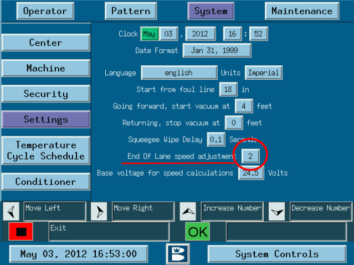
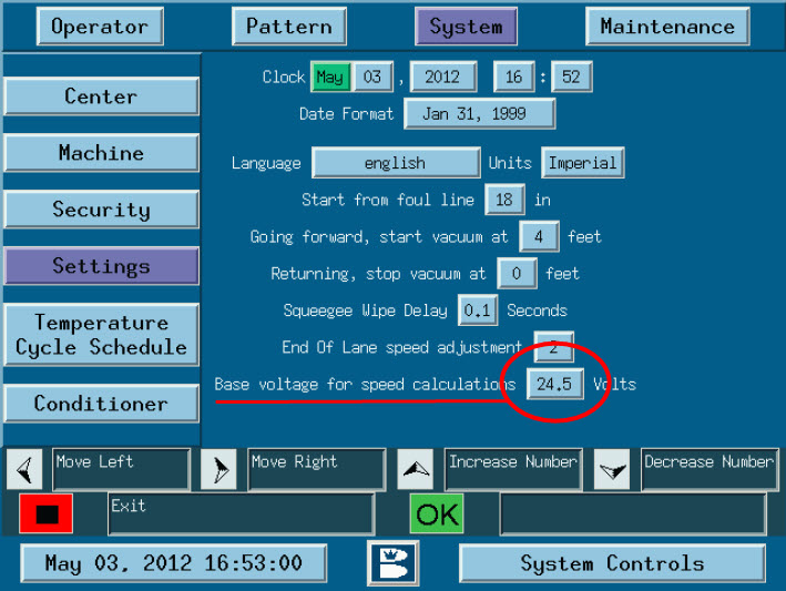
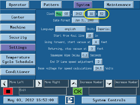
To make an
adjustment to the base speed of the machine you must go to the GUI and navigate
to the System > Settings area. The Base voltage is set by raising or
lowering the voltage in the Base Voltage for Speed Calculations box, (Figure
#1). Default setting is 24 volts, start by raising the voltage one full volt at
first, then 0.5 volts each time afterword until you reach the desired
parameters of cleaning mode that the machine pattern is in.
If the
adjustment limits are reached and you still cannot reach the desired time
parameters you will need to do a FMAX Trim Pot adjustment. Please refer to the FMAX Trim Pot Adjustment instruction sheet.
Figure #1
Revision Date:
3/17/16 - Released to KB
1.3.3.4. Envoy Charging System Troubleshooting
Environment:
Envoy battery charging system
Applicable Version(s):
All
Procedure:
See attachment
Applicable Files:
'Envoy Charging System Troubleshooting.pdf'
Related Information and Links:
Revision Date:
10/04/2018 - Released to KB
1.3.3.5. Envoy GUI Losing 4 Hours of Time
Environment:
Envoy Lane Machine
Applicable Version(s):
All
Issue:
Envoy GUI does not hold time, looses 4 hours of time
Cause:
Advantech GUI Motherboard Bug. The only time that the GUI loses 4 hours is just the first reboot after someone manually changes the time in the System Settings screen (such as when daylight savings time changes). It happens infrequently.
Solution:
How to set your time and date to compensate for the 4-hour
loss.
Tools needed: None
The Advantech Motherboard for the Envoy lane machine has a
bug where the board reverts back 4 hours of time after the time has been
changed and a re-boot of the GUI happens.
The work around for this is to set your time up four hours
ahead when changing daylight savings time. Then, reboot one time and the time will
revert back 4 hours. The time is now set and will not change when powered
down and/or re-booted.
Remember, when changing the time, always add 4 hours to the
time and then re-boot the GUI.
Advantech is working on this issue at the present time.
Revision Date:
3/19/16 - Released to KB
1.3.3.6. Envoy Power Type Change Over Procedure
Environment:
Envoy Lane Machine
Applicable Version(s):
All
Procedure:
The AC/DC
power supply is designed to provide a level of back up protection in the event that
the batteries fail to get recharged after use, or hold a charge as they end
their life cycle.
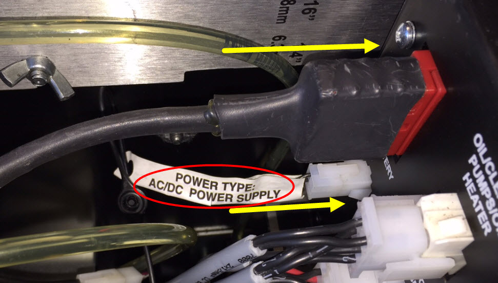
The Envoy AC/DC Power Supply is installed below the electrical enclosure before the lane machine is shipped. To switch to using the AC/DC Power Supply, first disconnect the AGM or Lithium Battery power cable and power type jumper from the electrical enclosure.
Locate
the AC/DC Power Supply red 24VDC power cable connector (usually coiled just
under the left side of the electrical enclosure).
Connect the AC/DC Power Supply cable and power type jumper to the electrical enclosure.
The input
cable of the AC/DC Power Supply is already connected to the Twist-Lock
connector on the rear cover. Connect the Twist-Lock end of the supplied 125’
power cord into the matching connector in the rear cover. Place the power cord
ring into the Cord Kill assembly. Connect the other end of the 125’ cable into
a grounded power supply with 100-240VAC, 50/60 Hz. The Envoy machine should now
be powered by the 24VDC nominal output of the AC/DC Power Supply and operate
similarly as if it were powered by a battery.
The operator will now need to manage the power cord so that it does not get trapped under the lane machine during operation.
The 125’ power cord should only be connected to the AC/DC Twist-Lock connector on the rear cover when the Envoy is in the operating position. This cord should be disconnected before the machine is lifted into the transport position.
If the batteries are not fully charged, the AC/DC Power Supply cable and power type jumper should be disconnected from the electrical enclosure after running the lanes and the battery power cable and power type jumper should be reconnected to the electrical enclosure. The battery charger should then be connected and turned on to charge the batteries.
Notes:
This procedure would be the same when upgrading your battery from a AGM to a Lithium battery. The Power Type plug is very important.
If you upgraded from a AGM to a Lithium battery and did not change the power type plug the machine may run a bit slower, it will run but at a slower pace.
If you forgot to change the AC power type plug to a battery type power plug of any type the lane machine vacuum will run when the Okay button is pressed on the approach. When using AC power the vacuum runs continually like a Authority22 does since it is AC and has no worry with battery life. It is designed to run like this when using AC power. Battery power will give you options to delay the vacuum start time.
Revision Date:
10/02/2015 - Released to KB
1.3.3.7. Installing the Emergency Run Display and Cable for the Envoy
Posted Values
Environment:
Envoy Lane Machines
Applicable Version(s):
All
Procedure:
The eRUN Display provides a way to
continue to run the Envoy lane machine in an emergency situation without the
GUI. The eRUN will only be able to run pattern #1, so it is a good idea to make
sure that pattern #1 is your most popular pattern set in the clean and
condition mode. Also, follow the End of Lane Speed Adjustments noted after the
following basic Installation and Operation Instructions.
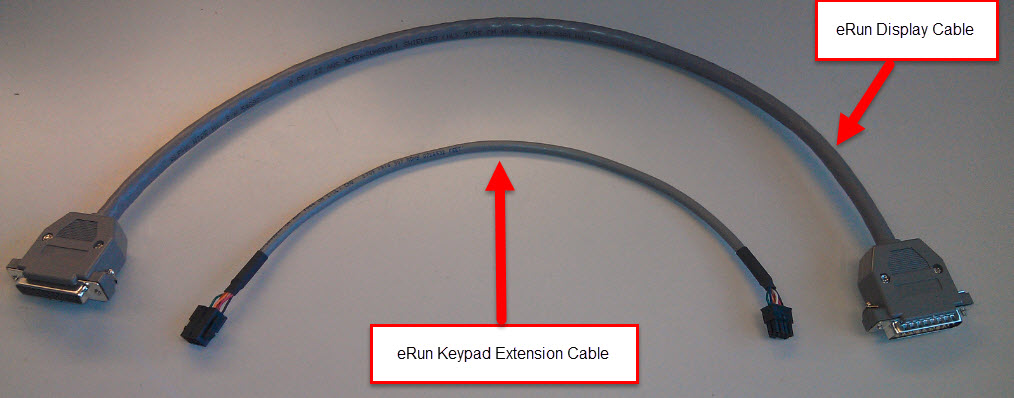
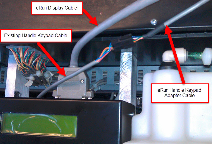
eRUN Display Installation Instructions
1. Turn the power off to the Envoy using the
switch on the LH side cover. 2. Disconnect the non-functioning GUI and send it to the Brunswick for repair. (Contact Brunswick Electronic Repair or your Distributor if you are unsure of how to return electronic parts for repair.) 3. Locate the eRUN keypad extension cable (P/N 14-100899-000) from the eRUN package.
4. Connect one end of this cable to the
T-handle keypad cable that was just disconnected from the GUI (Emergency Run
Cable Connections figure is shown below).
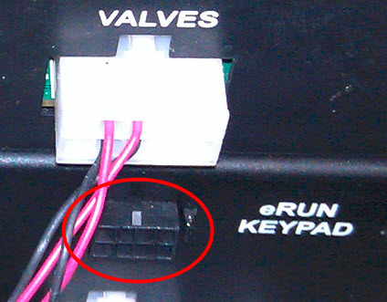
5. Connect
the other end of this cable into the “eRUN Keypad” port on the RH side of the
electronic enclosure.
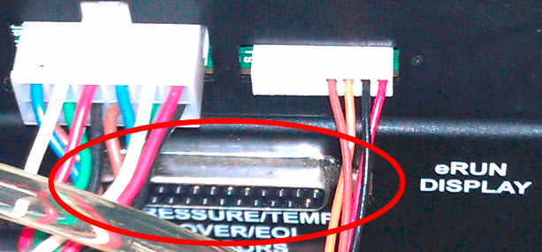
6. Locate the eRUN display cable (P/N
14-100897-000).
7. Connect the one end of this cable into the “eRUN Display” port on the RH side of the electronic enclosure.
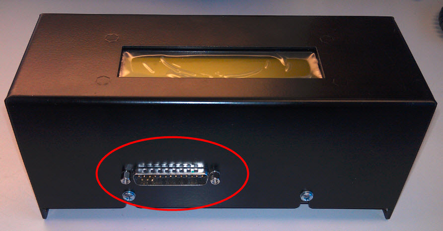
8. Connect the other end into the port on the eRUN box
9. Snap
the eRUN enclosure onto the GUI support, using the spring-loaded ball detect
similarly to the attachment of the GUI.
Note: Tighten down the screws on the display cable to the eRun emergency box
and zip tie the cables together once you have them connected to both the eRun
emergency box and electrical enclosure. This way you keep both cables together
and the cables connected to the eRun box so that they do not get lost. Keep
this “system” together in a safe place. If any one of these pieces are missing
the eRun emergency backup system will not work.
eRUN Operation
Instructions
1.Turn the power back on to the Envoy using the switch on the LH side cover.
2. Observe the 2-line eRUN Display text as it initially displays the firmware version and then indicates that the GUI is not detected and you are running in the eRUN mode.
3. Press the OK on the T-handle keypad as the eRUN text prompts you ‘Preparing Lane?’.
4. Observe the eRUN text as it is ‘Preparing’ (lowering the squeegee/duster cloth and setting the conditioner pressure).
5.Push the Envoy onto the lane when the eRUN text prompts you to put the machine onto the lane.
6.Press OK to start running that lane.
7.Repeat steps 3 through 6 for each lane that you choose to run.
8. Simple error messages will be displayed, but the eRUN has limited functionality and should be replaced with a functional GUI as soon as possible.
Reminder: Always have your favorite or most used pattern downloaded into the pattern #1 position as the eRun box only reads the #1 pattern position.
Applicable Files:
'eRUN_Installation_and_Operation.pdf'
Revision Date:
06/1/2017 - Released to KB
1.3.4. Envoy Tracktion Drive, End of Lane & Encoder Sensors
1.3.4.1. End of Lane Sensor ID: Removing, Replacing and Adjusting
Environment:
End of Lane Sensor Identification, Removal, Replacement and Adjustment.
Applicable Version(s):
All Version Authority22 and Envoy Lane machines.
Procedure:
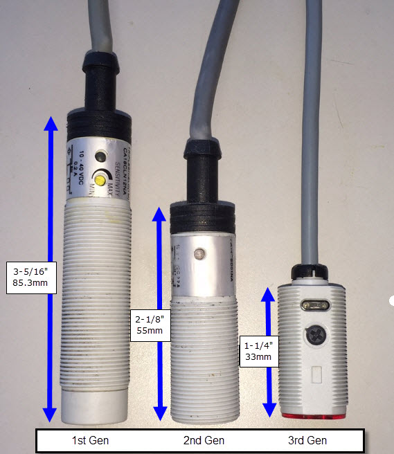
The Authority22 and Envoy lane machines have used different
types of "End of Lane sensors" since their inception. The current part number for
the sensor is 14-100235-091. This sensor (3rd Gen) can be used in both the Authority22 and Envoy
lane machines.
Authority22 End of
Lane (EOL) sensor types:
1st Generation was an adjustable type that was
3-1/8” long (85.3mm).
2nd Generation was a photo-optical type that was 2-1/8”
long (55mm) and is NOT adjustable.
3rd Generation (Current) is an adjustable type
that is 1-1/4” long (33mm).
Envoy End of Lane
(EOL) sensor types (Same as A22):
1st Generation was a photo-optical type that was
2-1/8” long (55mm) and was NOT adjustable.
2nd Generation was an adjustable type that was
1-1/4” long (33mm).
Authority22 1st
Generation End of Lane Sensor Replacement and Adjustment
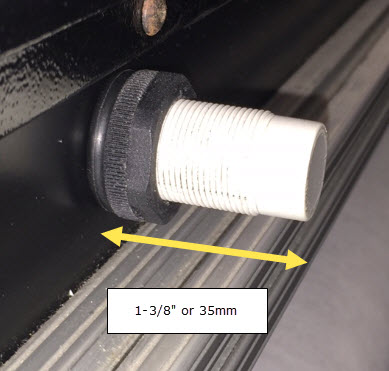
The Authority22 first generation End of Lane sensor is a Capacitive
Proximity Switch. The base is 3-5/16” long (85.3mm) and is adjustable.
Tools needed:
(2) 15/16” wrenches or adjustable wrench.
Replacing the 1st
generation (A22 Only) End of Lane Sensor
1. Place machine in transport position with the cover open
and power supply disconnected.
2. Loosen and remove nut at base of sensor.
3. Remove black O-ring from base of sensor.
4. Disconnect sensor cable from the quick-connect cable harness.
5. Pull sensor out from the top side of the machine and remove the second
O-ring on top side of the sensor.
6. Place an O-ring under the top-side nut and then install new sensor from top
side of the machine so that sensor extends 1-3/8" or 35mm beyond shield.
Note:The
sensor must be set in proper position for accurate operation.
7. Place the second O-ring on the sensor pushing it up to
the bottom side of the mounting shield.
8. Insert and tighten nuts at base of sensor.
*** Do NOT over tighten nuts ***
9.
Adjust sensor as needed.
Adjusting the 1st
generation (A22 Only) End of Lane Sensor
Tools Needed:
Small screwdriver included in the spare parts
kit.
An accurate measuring device
(2) 15/16” wrenches or adjustable wrench
Place machine in operating position with power supply
connected.
This sensor must be set in proper position and at the
proper sensitivity for accurate operation.
To adjust the physical position of the sensor, verify that the sensor extends
1-3/8" (35mm) beyond shield at its base and adjust if necessary using the
15/16" wrenches or adjustable wrenches.
To adjust the sensitivity of the sensor, use a small screwdriver supplied in
spare parts kit, to increase (clockwise) or decrease (counterclockwise) the
sensitivity adjustment (yellow slotted dial). The factory-set position is with
the slotted dial at approximately 3 o’clock.
While the machine is on the approach, the LED on the sensor should be Off.
Rotate the sensitivity adjustment clockwise so the LED turns On and then
counterclockwise so it is Off. Place finger underneath sensor and the LED
should turn On and then Off once the finger is removed. If the light stays
on, then adjust sensitivity down (counterclockwise).
Run the lane machine to verify proper sensitivity adjustment, if it returns
too early then increase the sensitivity.
Verify that the end-of-lane sensor does not contact the lane when the front
lane-to-lane castors drop into the gutter at the foul line.
Authority22/Envoy
2nd generation End of Lane Sensor Replacement and Adjustment
The Authority22 Second Generation End of Lane Sensor is a Defuse
Reflective Sensor. The base is 2-1/8” long (55mm) and no adjustment is
necessary.
Replacing the 2nd
generation End-of-Lane Sensor
Tools needed:
A wrench
Parts
needed:
Replacement EOL sensor (Part Number 14-100235-000).
Place
machine in transport position with the cover open and power supply
disconnected.
Loosen
and remove nut at base of sensor.
Remove
black O-ring from base of sensor.
Disconnect
sensor cable from the quick-connect cable harness.
Pull
sensor out from the top side of the machine and remove the second O-ring on top
side of the sensor.
Place
an O-ring under the top-side nut and then install new sensor from top side of
the machine.
Place
the second O-ring on the sensor pushing it up to the bottom side of the
mounting shield
Insert
and tighten nuts at base of sensor until the end of the sensor is just even
with the bottom edge of the lower nut.
*** Do NOT over tighten nuts ***
Adjusting the 2nd
generation End of Lane Sensor
There is no adjustment necessary for this type of End of
Lane Sensor. Check and make sure the sensor is operational by using the GUI and
navigating to the Maintenance > Diagnostics > Sensors screen. Check
the sensor by placing your hand under the sensor to check and see if the End
of Lane sensor button on the GUI screen is changing color state. If so the End
of Lane Sensor is working fine.
Authority22/Envoy
3rd Generation End of Lane Sensor Replacement and Adjustment
The Authority22 third generation End of Lane Sensor is a Defuse
Reflective Sensor. The base 1-1/4” long or 33mm and is adjustable.
Replacing
the 3rd generation End-of-Lane Sensor
Tools needed:
Adjustable wrench
Parts
needed: Replacement EOL sensor (Part Number 14-100235-000).
Place
machine in transport position with the cover open and power supply
disconnected.
Loosen
and remove nut at base of sensor.
Remove
black O-ring from base of sensor.
Disconnect
sensor cable from the quick-connect cable harness.
Pull
sensor out from the top side of the machine and remove the second O-ring on top
side of the sensor.
Place
an O-ring under the top-side nut and then install new sensor from top side of
the machine.
Place
the second O-ring on the sensor pushing it up to the bottom side of the
mounting shield
Insert
and tighten nuts at base of sensor until the end of the sensor is just even
with the bottom edge of the lower nut.
*** Do NOT over tighten nuts ***
Adjusting the 3rd
generation End of Lane Sensor
This style End of Lane Sensor has an adjustable
sensitivity control that has been preset to the position shown below by
Brunswick. The range of this adjustment screw is 270 degrees (135 degrees to
either side of the position shown).
Do not force this screw more than 1/3 turn past
the position shown.
Sensitivity Control Operational Indicator
(Yellow) Power Indicator (Green)
This sensitivity control should result in a
steady signal (shown by the yellow operational indicator light) while the red
end of the sensor is within 4-6” of the lane or approach surface. This yellow
operational indicator light should turn off, indicating that the sensor has
gone past the pin deck end of the lane, if the lane surface is greater than 6”
from the red end of the sensor.
Note: The mounting nut
will cover the sensitivity control when the sensor is properly mounted on the front
of the lane machine. Also, make sure to re-use the black O-rings from the original sensor while installing the new sensor.
Check of GUI Settings, Run Time Log and
Observing Travel in Pin Deck (no meter or opening of enclosure).
STEP 1: When encountering any Envoy
Travel Speed or Stalling issues, first determine the selected Travel Speed in
the Pattern Design Parameters screen of the GUI. Record the selected speed below: GUI Software version: ___
Quick Clean
______ ? (62 – 72 second Run
Time Range, Target 67 seconds)
Heavy Clean
______ ? (70 – 80 second Run
Time Range, Target 74 seconds for v3.04 GUI software)
Max Clean
______ ?(78 – 88 second Run
Time Range, Target 82 seconds for v3.04 GUI software)
STEP 2: Review the Run Time Log to see if the
Actual Run Times are in the proper time ranges selected above. It is best to record the data for lane #5,
lane #15 and the last lane in the space below:
Lane #5 Run
Time:Avg _____ , Hi _____ , Lo _____ ,
3rd _____ , 2nd _____ , Last _____ seconds
Lane #55 Run
Time:Avg _____ , Hi _____ , Lo _____ ,
3rd _____ , 2nd _____ , Last _____ seconds
Last Lane
Run Time:Avg _____ , Hi _____ , Lo
_____ , 3rd _____ , 2nd _____ , Last _____ second
STEP 3: Adjust the Base Voltage for Speed
Calculation in the GUI SYSTEM SETTINGS screen. Every 0.5 Volt increase should reduce the Run
Time Speed by ~1.5 seconds (unless the Envoy is nearly stalling in the pin
deck). Run the Envoy again at least 5
lanes after making this adjustment to see if the run time changed as
expected. Always ignore the slower run
time of the first lane, unless it stalls in the pin deck.
STEP 4: Observe the travel of the Envoy as
it enters the pin deck. It should
gradually slow down ~10 feet before the end of the lane and continue to move
smoothly without any hesitation or risk of stalling before it reaches the end
of the lane and reverses direction. If
the Envoy stalls, note the position of the rear cover in relation to the pin
spots (Did the rear cover go past the head pin before stalling? 2” beyond 2-3 spots is normal rear reverse
point). Report if any pins are wedged by the side covers in the flat gutters. Does this happen on the same lane? Clean drive wheels with IPA 99 to remove accumulated cleaner or conditioner which would cause slipping.
STEP 5: Increase the End of Lane speed
adjustment in the
GUI SYSTEM SETTINGS screen up to the maximum setting of +15. This setting only affects the last 12” of
travel at the very end of the pin deck. Don’t be afraid to increase this setting in increments of 5 since the
brakes will be applied very aggressively to prevent the machine from coasting
past the end of the pin deck with the correct full CCW setting of the KB speed
control board DECEL trimpot.
If you have
increased the Base Voltage for Speed
Calculation near 27 volts in the GUI SYSTEM SETTINGS screen, and the End of Lane speed adjustment is +15 and
you are still observing slow, inconsistent travel speed or stalling, then you
may need a Voltmeter to continue troubleshooting to determine if the KB speed
control Board needs to be adjusted or replaced, if the traction motor is
pulling excess current, etc. Inconsistent
run times are usually caused by a bad KB speed control board, while rapidly
decreasing speeds may becaused by a
bad traction motor.
STEP 6: Use a voltmeter to check the KB speed control board output to Traction Motor during the Diagnostics
Drive Test mode. (See below procedure - “Envoy
Traction Motor Voltage Measurement Procedure” showing how to attach the voltmeter
and warm up a few lanes)
Note: This check is just the first
indicator that the KB speed control board output is correct. It can easily be run on the approach, but it
doesn't assure proper function on the lane where the GUI System Settings, squeegee pressure adjustment, and other variables are involved.
< Difficult travel issues require more information from the following steps to resolve >
STEP 7: Use the following
“Adjustment of the FMAX trimpot on the KB speed control board” procedure
if diagnostics voltage is significantly less than 14.2V (Remember that the Base
Voltage for Speed Calculation and the End of Lane speed adjustment do not
affect the KB speed control board output to Traction Motor during the
Diagnostic Drive Test mode. The GUI
System Settings only affect the KB speed control board output to Traction Motor
while running an actual lane.) Skip to
step 8 if this voltage is above 14.0V.
STEP 8: Check Voltage while running a combination Clean & Condition mode on the lane (close covers and tape voltmeter to T-Handle as close to the handle end as possible so you can see the reading while the Envoy is under the pin deck in step 9). Observe the KB speed control board output voltage to Traction Motor while the Envoy is moving at a steady speed on the center 20-40 foot section of the lane. Compare to chart below during Forward Travel (squeegee Down) and Reverse Travel (squeegee Up). Record these voltages and the Run Times for 10 lanes.
STEP 9: If the Envoy hesitates or stalls in the pin deck, check the KB speed control board output voltage to Traction Motor at the very end of the lane while the Envoy is traveling slowly before it reverses. This voltage should never be less than 5 volt on the pin deck. Be careful to get out of the way when the Envoy returns to the foul line. Trip the Cord Kill Switch or Emergency Stop button if you need to stop the travel of the Envoy.
STEP 10: Check the Traction motor current with a Clamp-on Ammeter and compare to the chart above to see if the traction motor may need to be replaced. The covers will need to be left open to view the Ammeter while it is clamped over one of the individual blue or brown wire near the “Drive Motor” connector on the left side of the enclosure. A current reading above 3 Amps during the Diagnostic drive test mode on the approach or above 10 Amps while running a combination Clean & Condition mode on the lane may indicate that the traction motor needs to be replaced.
Envoy Traction Motor Voltage Measurement Procedure
Tools needed:
Multi-meter that will read DC volt and DC Amperage.
Small pocket type flat blade screwdriver.
Sealer or whiteout for sealing the trim pot.
Phillips screw driver to remove the cover on the electrical enclosure.
Note: Measuring the KB
speed control board output voltage to Traction Motor should be made when the
Envoy is connected to the AC/DC Power
Supply. This will assure a steady 26.5 VDC supply to
avoid any variables from a discharged battery. If time doesn't allow for this,
the next best option is to run with a fully charged Lithium battery.
To switch to using the AC/DC
Power Supply, first disconnect the AGM or Lithium Battery power cable and power
type jumper (#1) from the electrical enclosure (#2). Then locate the AC/DC Power Supply red 24 VDC
power cable connector (usually coiled just under the left side of the
electrical enclosure). Connect the AC/DC
Power Supply cable and AC/DC power type jumper to the electrical enclosure.
(See Figure #1)
Figure #1
Then, run 6-8 lanes in a clean and condition mode to warm up the drive motor.
Next, locate
the “Drive Motor” connector on the same side (left side looking from handle) of
the enclosure as the AC power plug was installed. Leave the drive motor
connector plugged into the enclosure. Take
your voltmeter leads and put the red lead into the connector wire for the brown
wire, and the black lead into the blue wire on the connector like the
illustration below (Figure #2). Select on your volt meter “DC Voltage” for
this test.
Figure #2
Using the
GUI, navigate to “Maintenance” > “Diagnostics” > “Drive”, then make sure
the “Forward” is selected on the right hand button display. Now select and
press “Drive” on the left hand button. This should start the drive motor and continue
to run at a set medium speed for 20 seconds. The voltmeter should read DC voltage from 14.0 to 14.3 VDC. If it is below 14.0 VDC or you have had to adjust
the Base Voltage for Speed Calculation near the maximum 27.0 setting, then the
FMAX trimpot of the KB speed control board will need to be adjusted to measure
14.2 to 14.8 VDC while running on the approach in the Diagnostic Drive Test mode
(see next process).
Last Steps: Opening Enclosure to adjust or replace KB board
Adjustment of the
FMAX trimpot on the KB speed control board (inside
the Electrical Enclosure)
Remove the top cover of the
electrical enclosure
by removing the six screws on the top of the enclosure.
Check for any loose terminal
connections or discolored wires inside the electrical enclosure.
- Replace
the old “Y” terminal adapter on the Charge Relay with the new version Ring
Terminal connected to the Charge Circuit Breaker. Replace
any suspect terminals, relays, circuit breakers or discolored wires.
- Check
the tightness of the terminal strip nuts or any other electrical connections.
Locate the
KB speed control board “FMAX” trim pot. This is the first trim pot from the top
of the KB speed control board (see Figure #3). While the Envoy is running in the
Diagnostic drive test mode, adjust this trim pot to 14.5 VDC to 14.8 VDC. Once
this has been obtained, go back to your base speed adjustment and start at the
default voltage of 24.0 volts and adjust voltage for speed from there.
Be sure to
seal the trim pot with a sealer from an electronics shop or use “White-Out”
correction liquid from an office supply store. Otherwise, the adjustment may change from normal everyday transportation.
Figure #3
Again, below are the
parameters for each cleaning mode.
62-72 Seconds Quick Clean
70-80 Seconds Heavy Clean
78-88 Seconds Max Clean
Note:Please
make sure you run 6 to 8 lanes to warm up the Envoy drive motor and wet the
absorbent wiper so that you can get a more accurate time measurement.
Remove the KB speed control
board and replace it with a new 14-100822-800 part that has been pre-set by
Electronic Repair if the speed or end of lane performance is still
inconsistent.
Revision Date:
12/16/2016 - Released to KB
1.3.5. Graphical User Interface (GUI) Envoy
1.3.5.1. Conditioner Pump Cycling Continuously
Environment:
Envoy Lane Machines
Applicable Version(s):
GUI Software version 3.01, 3.01t, 3.01w, 3.02
Issue:
Conditioner
pump running all the time will not shut off. Or, the pump cycles on and off
Temperature cycle button on operator’s screen shows Off.
Cause:
In our early Envoy software, if you had turned on the
temperature cycle on the operator’s screen or the temperature cycle was
activated because of the temperature cycle scheduler and you navigated in the
GUI to the Maintenance, then Diagnostics area, the temperature cycle
override button would change from “On” to “Off”. However, the conditioning pump and
temperature cycle would still be running even when it said it was off.
The bug is that it changed the On on the temperature
cycle override button once you navigated to the diagnostics area to Off causing
the pump to run continually. This could cause premature wear of the pump if not
addressed.
Solution:
We now have newer software to fix this, but until your
machine is updated you will need to:
1. Highlight the temperature cycle
button and press the 'OK' button to turn it from Off to On.
2. Then, press the OK button one more additional time to turn it from On back to Off and this will
get the temperature cycle button back in sync.
To understand how this happens, let’s demonstrate how it happens.
1. Highlight
the temperature cycle button and turn the temperature cycle to On.
2. Navigate to the Maintenance > Diagnostics area. The pump should turn off
when entering into the diagnostics area.
3. Leave the diagnostics area and navigate
back to the operator’s screen. The pump should turn back on, and then you will see
the temperature cycle button it should say it is Off.
Revision Date:
11/22/2016 - Released to KB
1.3.5.2. Envoy GUI White Screen Common Causes
Environment:
Envoy GUI
Applicable Version(s):
All
Issue:
GUI is showing a white screen
Cause:
See attachment
Solution:
See attachment
Applicable Files:
'White Screen Issues and ERC Fixes.pdf'
Related Information and Links:
Revision Date:
05/30/2019 - Released to KB
1.3.5.3. Making a Back Up File for the Envoy Lane Machine
Environment:
Envoy Lane Machine Graphic User Interface Pattern and Settings
Applicable Version(s):
All
Procedure:
Making a backup file
for the Envoy Lane Machine
1. Make sure the Graphic User Interface (GUI) is at
the operator’s screen. (see Figure #1)
Figure #1
2. Insert Thumb Drive (Flash Drive) into the USB
port on the left hand side of the GUI. (see Figure #2)
Note: Make sure you use an empty Thumb Drive / Flash Drive
with no folders or files on it. Leaving other lane machine “backup” folders on
a thumb drive may cause inadvertent installation of another centers lane
machines settings.
Figure #2
3. The “Import Data / Export Data” screen will
appear. Default is “Export Data” Press the green “Okay” to proceed to the next
screen. (see Figure #3)
Figure #3
4. Now you are at the "Export Data" screen, press the green “Okay”
button one more time. (see Figure #4)
Figure #4
5. You will see this screen for a few seconds, the
words will be missing but it is okay, then the “Import Data” / “Export Data”
screen the words come back. At this time, you can remove the Flash drive /
Thumb Drive from the GUI. This part is now done. You now have a folder on your thumb drive called "backup" this folder will have all your patterns and settings data. (see Figure #5)
Figure #5
Finding and sending
the “backup” file in email.
Insert your “Thumb Drive / Flash Drive” into
your personal computer. Open your drive and look for a folder called “backup”.
Double click on this “backup” folder to open it.
You should see some files listed in this folder. Scroll down to the bottom of this folder and
there will be a zipped folder called “backup.1.zip”. This is the folder that we
will need sent to us for troubleshooting.
Send this “backup.1.zip” folder to techsupport@brunswickbowling.com
and add in the subject line the reference number in the email we have been
corresponding. Example is below.
Note: Always store
the centers backup files in a folder designated for that center and date it,
leaving “backup” folders on your thumb drive may lead to loading some other
centers pattern and settings inadvertently being loaded into another centers
lane machine. All Authority22 and Envoy lane machine back up folders are called
“backup” so they need to be filed away and separated.
Revision Date:
3/6/2017 - Released to KB
1.4. Brunswick Phoenix Lite
1.4.1. Phoenix Lite LT4 Buffer Brush Drive Pin Wear
On some Buffer Brush assemblies (294-116-065) used in the Phoenix Lite LT4 Lane Machine, we have seen premature wear on the pins and on the correlating holes in the drive pulley. This wear is caused by poor engagement of the pins into the drive pulley. All Phoenix Lite LT4 Lane Machines manufactured before 5/5/2014 could potentially have the drive pin wear issue.
If wearing is occurring between the pins and the drive pulley holes, the buffer brush will begin to make a scraping noise as it is operating. Continued wear will allow the buffer brush to disengage and fall out of the lane machine.
The pictures below, shows the wear of the drive pulley and engagement pins of the buffer brush hub (Figure 1)
Figure 1
It has been determined that the cause of this wear is due to poor engagement of the pins of the buffer brush hub into the drive pulley. This poor engagement is due to the pins being pressed too far into the buffer brush hub during the manufacturing process.
We recommend that you inspect the pins in the buffer brush assembly and the drive pulley for wear as shown in Figure 1.If no wear has occurred, measure the height of the pins from the surface of the hub. The pins must protrude at least a 1/4" [6.35mm] but no more than 17/64” [6.74mm] from the surface of the hub. (Figure 2)
Figure 2
If upon inspection, there is wear showing on the pins of the buffer brush hub, in the holes of the drive pulley, or the pins measure less that 1/4” from the surface of the hub, contact Brunswick Technical Support 800-937-2695 or techsupport@brunswickbowling.com.
If you have questions regarding this or any other Service Bulletin, please contact the Brunswick Technical Support at 1-800-937-2695 or 231-725-4966, or Email techsupport@brunswickbowling.com.
1.5. Incorrect Pressure Readings or No High Conditioner Pressure Warning
Environment:
Conditioner pressure sensor and GUI
Applicable Version(s):
All Versions A22 and Envoy
lane machines
Issue:
Incorrect pressure readings or no high conditioner pressure warning.
Cause:
Bad Conditioner pressure sensor and/or bad conditioner pressure cable connections.
Solution:
See attachment
Applicable Files:
'Incorrect Pressure Readings or No High Conditioner Pressure Warning.pdf'
Revision Date:
09/26/2018 - Released to KB
1.6. Low or High Pressure Errors on Brunswick Lane Machines
Environment:
Brunswick Lane Machines (A-22, Envoy, MAX)
Applicable Version(s):
All
Issue:
Inconsistent conditioner volume, low or high-pressure errors.
Cause:
The pressure for the Accumulator Diaphragm is at or below 10 PSI.
Solution:
In order to properly diagnose this issue, we we will need to remove the accumulator diaphragm to verify the PSI.
When accumulator is completely low on PSI the Gauge needle will jump from approximately 25 PSI to up to 60 PSI. Triggering a High-pressure error.
Procedure to Remove and Verify Pressure
Disconnect wires connection from the Pressure sensor and temperature sensor from the accumulator rail.
Remove the two ½ inch nuts that holds the accumulator rail assembly.
Turn the Accumulator rail in a vertical position. Remove the hex cap to expose the stem valve.
Check the accumulator pressure using a tire pressure gauge. Should read 10 to 10.5 PSI.
If the pressure is below 10 PSI you will need to inflate the accumulator bladder using a bicycle air pump. If you exceed 10 PSI, simply push the stem valve very quick to deflate until you reach 10 to 10.5 PSI.
Once completed re install the accumulator rail and reconnect the pressure and temperature sensors.
Applicable Files:
N/A
Related Information and Links:
N/A
Revision Date:
08/25/2020 - Revised document to web format.
09/17/2018 - Released to KB
Interruption of communication inside the control box between the logic and relay boards.
Solution:
If this error occurs, turn the power switch off then on. If the error is cleared the machine is okay for operation. If the problem persists follow these instructions in the attached document.
Applicable Files:
'LT4 Error Code_4 Troubleshoot.pdf'
Related Information and Links:
Revision Date:
10/26/2018 - Released to KB
1.9.2. Phoenix LT4 not Conditioning
Environment:
Phoenix LT4 Lane Machine
Applicable Version(s):
All LT4 Lane Machines
Procedure:
The Phoenix Lite LT4 lane machine can suddenly stop conditioning. This issue may occur if the tank
was removed (for cleaning or changing wicks) and reinstalled incorrectly in the
machine.
The tank must be mounted correctly on the support tube so that it rests properly against the transfer roller. An improperly mounted tank will ultimately result in the conditioner not being applied to the lane surface. It is possible to align the tank with its retaining bracket, yet still install the tank incorrectly. Refer to Figures 1 and 2.
It is easiest to check for proper
mounting with the machine in the upright or storage position. In this position
you can see the bottom of the oil tank and the support tube that it is resting
on.