1. Brunswick GS
1.1. Brunswick GS-92 Pinsetters
1.1.1. Gamesetter I/O Dip Switch Settings
1.1.1.1. Dip Switch Settings
 
Title: Consolidated I/O Dip Switch Settings 1 and 2.
Environment: GS Consolidated Pinsetters with Consolidated Electronics.
Applicable Version(s): All GS Pinsetters with Consolidated Electronics.
Issue: No Communication To Scorer / No Correct Pinsetter Operation.
Cause: Dip Switches Are Not Set Correctly.
Solution:
(Switch 1)
(Address Switch)
Must be set correctly set for the board to communicate with your scoring system. Using the board that you are replacing as a guide, set SW 1 to the same settings.
 
(Switch 2)
(Options Switch)
Must be correctly set for the board to operate the pinsetter correctly. Using the board that you are replacing as a guide, set SW 1 to the same settings.
Related Information and Links: I/O PCB Electronic Repair Part Number 47-142815-800
1.1.1.2. Dip Switch Settings for GS92 with Sync Scoring
Environment:
Dip switch settings of the Gamesetter pcb.
Applicable Version(s):
All GS 92 pinsetter and Sync scoring combinations.
Document Description:

This following explains the proper dip switch settings of a Gamesetter IO pcb in order to communicate to the Sync scoring system.

Dip switch 1 - off

Dip switch 2 - on

Dip switch 3 - off

Dip switch 4 - off

Applicable Files:
Related Information and Links:
Revision Date:
12/29/15 - Released to KB

 
1.2. Brunswick GS-98 Pinsetters
1.2.1. 24v Lane (Line) Power Relay will not Energize, and Receiving an EJ Code
Environment:
High Voltage box
Applicable Version(s):
GS 98 Pinsetters
Issue:
The 24v Lane (Line) power relay will not energize, and a EJ code presents itself whenever it attempts to turn on.
Cause:
The masking unit switch is turned off or there is faulty masking unit switch wiring.
Solution:

Turn the masking unit switch on and ensure the wiring is not faulty.


Revision Date:


1.2.2. Consolidated Electronics
1.2.2.1. GS Consolidated CPU PCB
 
Title: Consolidated CPU PCB Dip Switch Settings; Switch 3 Lane Assignment/Switch 4 Lane Characterization
Environment: GS 98 Pinsetters
Applicable Version(s): All GS Pinsetters with Consolidated Electronics.
Issue: No communication to scorer / Pinsetter will not operate correctly
Cause: Dip switches are set incorrectly
Solution:
(Switch 3)
(Lane Assignment Switch)
Must be correctly set for the board to communicate with the scorer. Using the board that you are replacing as a guide, set switch 3 to the same settings.
  
(Switch 4)
(Lane Characterization Switch)
Must be correctly set for the board to operate your pinsetter correctly. Using the board that you are replacing as a guide, set switch 3 to the same settings.
  
1.3. Brunswick GS-X Pinsetters
1.3.1. GSX Peripheral Controller Log Abbreviation Explanation for "RSTB" and "SETB"
Environment:
Sync with GSX Pinsetters
Applicable Version(s):
Sync 2.3.590 and all GSX pinsetters
Document Description:

The following 2 abbreviations will start to show up in version 2.3.590 and represent:

RSTB = The "Reset" button was manually pressed. This event is not logged in centers with A2 pinsetters in either mode, with or without the NPS(New Pins Solenoid).

SETB =  The "Set" button was manually pressed.


Revision Date:
6/20/2018 - Released to KB

 
1.3.2. GS-X Safety Controller Changes
Environment:
GS-X Safety Controller
Applicable Version(s):
Legacy and new versions of the Safety Controller
Document Description:
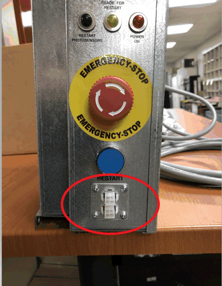
The previous version of the Safety Controller had (1) Interlock input for a door and (1) for the masking unit. With three interlocked doors and a masking unit per pair, we had to use a (2) Y-cables to get a total of (4) inputs.

Due to compliance efforts, we had to change it so that each door and the masking unit each had its own input.

In the near future you will see that there have been two inputs added onto the front of the safety controller. These are for the two division doors. The inputs on the bottom of the safety controller are for the ball return door and for the masking unit. In the future, once our stock of this version is used, all of the door inputs and the masking unit input will be on the bottom of the safety controller.
As you know, there are two versions of the safety controller. One for pinsetters with a masking unit, and one for pinsetters without a masking unit. The input for the masking unit is deactivated on the safety controller for pinsetters without a masking unit. Only the (3) door interlock inputs are activated.

For locations that regulations allow the Hold-to-Run switch:

Until our stock is used up of the temporary version that has the two additional inputs on the front of the safety controller, you will be sent (2) Y-cables and new firmware to reprogram the safety controller. You will replace the two inputs on the front with the Hold-to-Run switch. The new firmware you install in the safety controller and Y-cables will allow the safety controller and the Hold-to-Run switch to operate like it has in the past. Once we have stock of the safety controllers with all of the inputs on the bottom of the safety controller we will not send the Y-cables and firmware. You would assemble the Hold-to-Run switch as normal and use all the inputs on the bottom of the controller.
 

Applicable Files:
Related Information and Links:
Revision Date:
07/02/2019 - Released to KB

 
1.3.3. Nexgen Electronics
1.3.3.1. GSX Nexgen Keypad is Unresponsive
Environment:
GSX Nexgen Electronics
Applicable Version(s):
All
Issue:
The Nexgen keypad is unresponsive
Cause:
The Reset Button is stuck at the ball rack or there is a shorted wire from the Nexgen cable to connectors P4 and P20.
Solution:
See attachment
Applicable Files:
"Nexgen Keypad NonResponsive.pdf"
Related Information and Links:
Revision Date:
08/16/2018 - Released to KB

 
1.3.3.2. Functional Test Codes Appear on Nexgen Display After Installing CPU
 
Title: Functional Test Codes Appear on Nexgen Display After Installing CPU
Environment: GS-X Pinsetter with Nexgen Box   
Applicable Version(s): All Nexgen Boxes
Description: Locate and remove the test jumper labeled J7 on the CPU Board. This is located just under and to the left of the F3 fuse location. This will usually occur when a customer receives a CPU PCB that has been repaired by the Electronic Repair Center and the jumper has been left on from testing.
Applicable Files:
Related Information and Links:
1.3.3.3. Unable To Scroll Through Modes On Nexgen Box Display Using Keypad
 
Title: Unable To Scroll Through Modes On The Nexgen Box Display
Environment: Nexgen GUI display
Applicable Version(s):
Issue: Unable to scroll through modes of the Nexgen box display using the keypad.
Cause: Reset button or buttons at the ball rack in the bowlers area are stuck in the engaged position (Frameworx ball lifts with oval style reset buttons).
Solution: Dis-engage the reset button or buttons at the ball rack in the bowlers area.
Applicable Files:
Related Information and Links:
1.3.4. No GS-X Ball Detect Signal On Lane Pair
Environment:
Foul unit PCB
Applicable Version(s):
All GS-X Pinsetters with Nexgen Electronics
Issue:

No GS-X ball detect signal from left or right lane. The Zot foul unit is incorrectly set to the incorrect voltage on older units or the jumper is set to AMF and not BW on new style Zot foul units.


Solution:
Voltage should be set to 5 volts, not 12 volts on older units and the jumper must be set to BW on new style foul units not AMF.
Related Information and Links:
Revision Date:
3/10/16 - Released to KB
1.3.5. Setting Table
1.3.5.1. Pin Gripper Quick Release Procedure
Environment:
GS Setting Table
Applicable Version(s):
GS- pinsetters with black pin holders only.
Procedure:
This procedure describes how to remove the Pin Gripper from a Pin Holder without removing it from the setting table.
Applicable Files:
'Pin Gripper Quick Release Procedure.pdf'
Related Information and Links:
Revision Date:
01/03/2019 - Released to KB

 
1.3.6. Sweep Wagon
1.3.6.1. Sweep Release Adjustment
Environment:
GS-X pinsetter sweep wagon
Applicable Version(s):
All
Procedure:
See attachment
Applicable Files:
'Sweep Release Adjustment.pdf'
Related Information and Links:
Revision Date:
09/19/2018 - Released to KB

 
1.3.6.2. Troubleshooting 75 Error Code with GSX Pinsetter
Environment:
Nexgen box
Applicable Version(s):
All
Issue:
Pinsetter has displayed an error code 75
Cause:
The error code 75 is displayed if the pinsetter does not recognize that the sweep has dropped to the guard position.
Solution:
See attachment
Applicable Files:
'Troubleshooting Code 75 Error on GSX Pinsetters.pdf'
Related Information and Links:
Revision Date:
09/28/2018 - Released to KB

 
1.4. GS Ball Door Locking
Environment:
GS Series Pinsetter
Applicable Version(s):
All
Procedure:
See attachment
Applicable Files:
'GS Ball Door Locking.pdf'
Related Information and Links:
Revision Date:
10/26/2018 - Released to KB

 
1.5. How To Locate the Nexgen Box Firmware Version
Environment:
GS Nexgen Box
Applicable Version(s):
All
Procedure:
There are two ways to locate the firmware version. (This only applies to Nexgen Electronics)
  • Turn the main Nexgen Power Switch to the "OFF" position and then back to the ON position and wait for the display to boot up on the Nexgen Box. If a PF code appears then turn the RUN / Stop Switches Off and back On again to clear the PF codes.The firmware version will then be displayed.

If the PF code is not enabled the display will show the firmware version.

  • With power applied to the Nexgen Box. Switch both Run / Stop Switches to the "OFF" Position. Press the " Mode" key repeatedly until "Setup" appears on the display / Press the "Enter" key one time and the Nexgen Firmware version will be displayed.
Applicable Files:
Related Information and Links:
Revision Date:
12/7/2017 - Released to KB