|
Check of GUI Settings, Run Time Log and
Observing Travel in Pin Deck (no meter or opening of enclosure). - STEP 1: When encountering any Envoy
Travel Speed or Stalling issues, first determine the selected Travel Speed in
the Pattern Design Parameters screen of the GUI. Record the selected speed below: GUI Software version: ___
Quick Clean
______ ? (62 – 72 second Run
Time Range, Target 67 seconds) Heavy Clean
______ ? (70 – 80 second Run
Time Range, Target 74 seconds for v3.04 GUI software)
Max Clean
______ ? (78 – 88 second Run
Time Range, Target 82 seconds for v3.04 GUI software) - STEP 2: Review the Run Time Log to see if the
Actual Run Times are in the proper time ranges selected above. It is best to record the data for lane #5,
lane #15 and the last lane in the space below:
Lane #5 Run
Time: Avg _____ , Hi _____ , Lo _____ ,
3rd _____ , 2nd _____ , Last _____ seconds
Lane #55 Run
Time: Avg _____ , Hi _____ , Lo _____ ,
3rd _____ , 2nd _____ , Last _____ seconds
Last Lane
Run Time: Avg _____ , Hi _____ , Lo
_____ , 3rd _____ , 2nd _____ , Last _____ second - STEP 3: Adjust the Base Voltage for Speed
Calculation in the GUI SYSTEM SETTINGS screen. Every 0.5 Volt increase should reduce the Run
Time Speed by ~1.5 seconds (unless the Envoy is nearly stalling in the pin
deck). Run the Envoy again at least 5
lanes after making this adjustment to see if the run time changed as
expected. Always ignore the slower run
time of the first lane, unless it stalls in the pin deck.
- STEP 4: Observe the travel of the Envoy as
it enters the pin deck. It should
gradually slow down ~10 feet before the end of the lane and continue to move
smoothly without any hesitation or risk of stalling before it reaches the end
of the lane and reverses direction. If
the Envoy stalls, note the position of the rear cover in relation to the pin
spots (Did the rear cover go past the head pin before stalling? 2” beyond 2-3 spots is normal rear reverse
point). Report if any pins are wedged by the side covers in the flat gutters. Does this happen on the same lane? Clean drive wheels with IPA 99 to remove accumulated cleaner or conditioner which would cause slipping.
- STEP 5: Increase the End of Lane speed
adjustment in the
GUI SYSTEM SETTINGS screen up to the maximum setting of +15. This setting only affects the last 12” of
travel at the very end of the pin deck. Don’t be afraid to increase this setting in increments of 5 since the
brakes will be applied very aggressively to prevent the machine from coasting
past the end of the pin deck with the correct full CCW setting of the KB speed
control board DECEL trimpot.
If you have
increased the Base Voltage for Speed
Calculation near 27 volts in the GUI SYSTEM SETTINGS screen, and the End of Lane speed adjustment is +15 and
you are still observing slow, inconsistent travel speed or stalling, then you
may need a Voltmeter to continue troubleshooting to determine if the KB speed
control Board needs to be adjusted or replaced, if the traction motor is
pulling excess current, etc. Inconsistent
run times are usually caused by a bad KB speed control board, while rapidly
decreasing speeds may be caused by a
bad traction motor. - STEP 6: Use a voltmeter to check the KB speed control board output to Traction Motor during the Diagnostics
Drive Test mode. (See below procedure - “Envoy
Traction Motor Voltage Measurement Procedure” showing how to attach the voltmeter
and warm up a few lanes)
Note: This check is just the first
indicator that the KB speed control board output is correct. It can easily be run on the approach, but it
doesn't assure proper function on the lane where the GUI System Settings, squeegee pressure adjustment, and other variables are involved. < Difficult travel issues require more information from the following steps to resolve > - STEP 7: Use the following
“Adjustment of the FMAX trimpot on the KB speed control board” procedure
if diagnostics voltage is significantly less than 14.2V (Remember that the Base
Voltage for Speed Calculation and the End of Lane speed adjustment do not
affect the KB speed control board output to Traction Motor during the
Diagnostic Drive Test mode. The GUI
System Settings only affect the KB speed control board output to Traction Motor
while running an actual lane.) Skip to
step 8 if this voltage is above 14.0V.
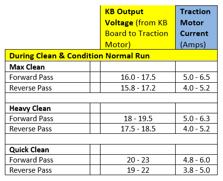
- STEP 8: Check Voltage while running a combination Clean & Condition mode on the lane (close covers and tape voltmeter to T-Handle as close to the handle end as possible so you can see the reading while the Envoy is under the pin deck in step 9). Observe the KB speed control board output voltage to Traction Motor while the Envoy is moving at a steady speed on the center 20-40 foot section of the lane. Compare to chart below during Forward Travel (squeegee Down) and Reverse Travel (squeegee Up). Record these voltages and the Run Times for 10 lanes.
- STEP 9: If the Envoy hesitates or stalls in the pin deck, check the KB speed control board output voltage to Traction Motor at the very end of the lane while the Envoy is traveling slowly before it reverses. This voltage should never be less than 5 volt on the pin deck. Be careful to get out of the way when the Envoy returns to the foul line. Trip the Cord Kill Switch or Emergency Stop button if you need to stop the travel of the Envoy.
- STEP 10: Check the Traction motor current with a Clamp-on Ammeter and compare to the chart above to see if the traction motor may need to be replaced. The covers will need to be left open to view the Ammeter while it is clamped over one of the individual blue or brown wire near the “Drive Motor” connector on the left side of the enclosure. A current reading above 3 Amps during the Diagnostic drive test mode on the approach or above 10 Amps while running a combination Clean & Condition mode on the lane may indicate that the traction motor needs to be replaced.
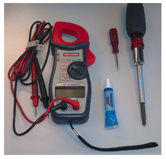
Envoy Traction Motor Voltage Measurement Procedure Tools needed: - Multi-meter that will read DC volt and DC Amperage.
- Small pocket type flat blade screwdriver.
- Sealer or whiteout for sealing the trim pot.
- Phillips screw driver to remove the cover on the electrical enclosure.
Note: Measuring the KB
speed control board output voltage to Traction Motor should be made when the
Envoy is connected to the AC/DC Power
Supply. This will assure a steady 26.5 VDC supply to
avoid any variables from a discharged battery. If time doesn't allow for this,
the next best option is to run with a fully charged Lithium battery.
To switch to using the AC/DC
Power Supply, first disconnect the AGM or Lithium Battery power cable and power
type jumper (#1) from the electrical enclosure (#2). Then locate the AC/DC Power Supply red 24 VDC
power cable connector (usually coiled just under the left side of the
electrical enclosure). Connect the AC/DC
Power Supply cable and AC/DC power type jumper to the electrical enclosure.
(See Figure #1)
Figure #1 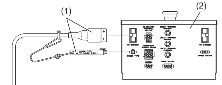
Then, run 6-8 lanes in a clean and condition mode to warm up the drive motor.
Next, locate
the “Drive Motor” connector on the same side (left side looking from handle) of
the enclosure as the AC power plug was installed. Leave the drive motor
connector plugged into the enclosure. Take
your voltmeter leads and put the red lead into the connector wire for the brown
wire, and the black lead into the blue wire on the connector like the
illustration below (Figure #2). Select on your volt meter “DC Voltage” for
this test. Figure #2 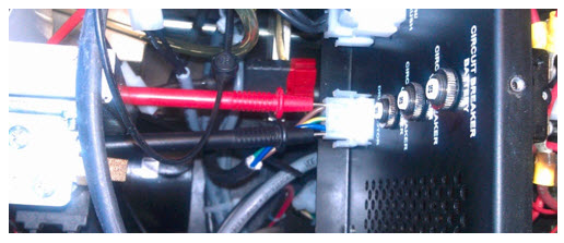
Using the
GUI, navigate to “Maintenance” > “Diagnostics” > “Drive”, then make sure
the “Forward” is selected on the right hand button display. Now select and
press “Drive” on the left hand button. This should start the drive motor and continue
to run at a set medium speed for 20 seconds. The voltmeter should read DC voltage from 14.0 to 14.3 VDC. If it is below 14.0 VDC or you have had to adjust
the Base Voltage for Speed Calculation near the maximum 27.0 setting, then the
FMAX trimpot of the KB speed control board will need to be adjusted to measure
14.2 to 14.8 VDC while running on the approach in the Diagnostic Drive Test mode
(see next process).
Last Steps: Opening Enclosure to adjust or replace KB board
Adjustment of the
FMAX trimpot on the KB speed control board (inside
the Electrical Enclosure) - Remove the top cover of the
electrical enclosure
by removing the six screws on the top of the enclosure.
- Check for any loose terminal
connections or discolored wires inside the electrical enclosure.
- Replace
the old “Y” terminal adapter on the Charge Relay with the new version Ring
Terminal connected to the Charge Circuit Breaker. Replace
any suspect terminals, relays, circuit breakers or discolored wires.
- Check
the tightness of the terminal strip nuts or any other electrical connections.- Locate the
KB speed control board “FMAX” trim pot. This is the first trim pot from the top
of the KB speed control board (see Figure #3). While the Envoy is running in the
Diagnostic drive test mode, adjust this trim pot to 14.5 VDC to 14.8 VDC. Once
this has been obtained, go back to your base speed adjustment and start at the
default voltage of 24.0 volts and adjust voltage for speed from there.
Be sure to
seal the trim pot with a sealer from an electronics shop or use “White-Out”
correction liquid from an office supply store. Otherwise, the adjustment may change from normal everyday transportation. Figure #3 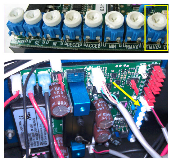
Again, below are the
parameters for each cleaning mode.
62-72 Seconds Quick Clean
70-80 Seconds Heavy Clean
78-88 Seconds Max Clean
Note: Please
make sure you run 6 to 8 lanes to warm up the Envoy drive motor and wet the
absorbent wiper so that you can get a more accurate time measurement. - Remove the KB speed control
board and replace it with a new 14-100822-800 part that has been pre-set by
Electronic Repair if the speed or end of lane performance is still
inconsistent.
|