1. Envoy Conditioning System
1.1. Conditioner Pump Head Removal and Replacement - Envoy
Environment:
Envoy Lane Machines Conditioning System
Applicable Version(s):
All Versions with Aquatec Conditioner Pump
Procedure:

Conditioner Pump Head Removal and Replacement – Envoy

Tools needed:

  • Allen wench size 1/8”

  • 3/8 Drive ratchet and 3/8” socket

  • #T-25 Torx screw driver

  • Card board

  • Terry cloth towels

  • Inch pound torque wrench (preferred but not necessary)

  • 1/4” and 3/8” vinyl caps to plug hoses

  • New pump head 14-100771-051 (Can be used for conditioning or cleaner pumps)

Instructions:

1. Ensure that the conditioner tank is no more than 1/3 full. (This first step is optional to reduce spillage of conditioner)

            a. In the GUI navigate to the “Operators Screen” Highlight the “Temperature Cycle” and turn it to “On”.

            b. While the pump is running, at the tank connection, disconnect the suction tube that goes to the inlet on the pump. (See Figure #1)

Figure #1


            c. When conditioner stops flowing back to the tank, turn off temperature cycle. Reconnect the suction tube on tank.

2. Removing the Conditioner Pump Assembly:

            a. Disconnect the electrical connections for the Pressure valve and the Conditioner Pump.

            b. Remove the 3 bolts that mount the pump assembly to the wall. Remove 1/8” Allen cap screw (Figure #2) attaching the conditioner pump bracket to the frame.

Figure #2


            c. Take your hand and hold onto the bracket, use your other hand to pry the shield away from the oil pump filter assembly (Figure #3) and at the same time raising the pump assembly up and out.

Figure #3

            d. Flip entire pump bracket and assembly upside down so that the 7 bolts that fasten the pump head are accessible (Figure #4).

            Note: Lay a piece of card board and terry cloth towel under the oil pump assembly to catch oil drippings and to use as a support to work on.

Figure #4


            e. Disconnect the inlet and outlet fittings/Tubes from the pump. Use the vinyl caps (if used) to plug the hose ends.

            f. Remove the 3 large Torx Head bolts (Figure #5) from the pump using a T-25 screwdriver. Retain these bolts, Remove the pump head from the pump motor.

Figure #5


             g. Place the new pump head 14-100771-051 on the pump motor. Align the 3 bolt holes and finger tighten the bolts.

3. Torquing the bolts:

            a. Preferred method: using a torque wrench and a T-25 bit, gradually torque the bolts to 27 in-lbs.

            b. Then ensure that all 7 bolts are at 27 in-lbs.

Alternate method: Using a manual screwdriver with a T-25 bit, gradually tighten the 3 bolts until they are very tight by hand. Using any wrench/lever or other mechanical means may over tighten and break the bolts or damage the pump! Ensure that all 7 bolts are very tight by hand.

Re-attach the fittings/tubes to the pump.

            a. Re-attach the hoses back onto the new pump head.
            b. Re-attach pump bracket to the frame.
            c.
Re-connect the electrical connections for the pump and the pressure valve.
            d.
In the GUI navigate to the “Operators Screen” Highlight the “Temperature Cycle” and press “Okay” to turn on the                   temperature cycle. Check for leaks.
            e.
Continue to run temperature cycle until all air has been removed from the conditioning system.

Revision Date:
12/20/2016 - Released to KB

 
1.2. Envoy Conditioner Pump Leaking from the Power Head
Environment:
Envoy Lane Machine
Applicable Version(s):
All
Procedure:

The Envoy conditioner pump head to motor bolts may not be tight on some conditioner pumps.

New Envoy lane machines and new conditioner pumps shipped between 2/1/2014 and 6/30/2014 may experience seepage of conditioner from the pump head to motor area. This can be fixed by tightening the pump head bolts to factory specifications.

Below are the instructions to remove and replace the conditioner pump and tighten the pump head bolts.

Tools Required: 

  • 3/8” Drive ratchet and 3/8” socket, or 3/8” wrench
  • 1/8” Allen wrench
  • T20 Torx socket
  • Torque wrench with Inch Pound or Newton Meter scale

Parts Required: None

Procedure: Note: It is not necessary to remove any of the conditioner pump hoses for this procedure.

1. Relieve the conditioner pressure using the lane machine GUI as follows: 

  • Select “Maintenance” > “Diagnostics” > “Conditioning.

  • Highlight the “Oil Pressure Valve” button and press “Okay” to relieve the oil pressure to zero as shown on the GUI digital gauge.

  • Check the analog gauge on the accumulator rail to verify zero pressure.

2. Locate and disconnect the electrical connector for the conditioning pump and the oil pressure valve.

3. Remove the small 10-32 x 1/2” long Allen head screw that secures the cross bracket to the conditioner pump oil/filter pan. Refer to Figure 1. 


4. Remove the three conditioning pump bracket bolts located on the outside wall next to the waste tank. Refer to Figure 2.


5. Push the oil pan wall away from the bracket so that the complete assembly can be lifted up and out of the oil pan tray. Refer to Figure 3.


6. Lay the assembly across the dividing wall between the oil pan and center tub section. Refer to Figure 4.


7. Using a torque wrench and T20 Torx socket, tighten the seven screws to 26-28 Inch pounds or 3.1 Newton Meter Nm. Start with one screw and alternate sides of the pump head when torquing the screws. Refer to Figure 5 for torquing sequence.


8. Reverse the pump removal procedure (step 5 – step 2) to re-install the conditioner pump and bracket assembly back into the machine. 

03/17/16 - Released to KB

 
1.3. Envoy Injector Rail / Heater Removal and Replacement
Environment:
Envoy and Authority22 Lane Machines
Applicable Version(s):
All
Procedure: Envoy Injector Rail / Heater Element Removal and Replacement

This procedure will show how to remove and replace the injector rail along with replacing the heater element. There are times when lane cleaner or other liquids are introduced into the conditioner tank by accident and the injectors on the injector rail can become clogged and cannot be cleared out by the injector blow out procedure.

This procedure should also be followed when replacing the heater element if it fails. The heater replacement instructions are at the end of this injector rail replacement instructions.

Tools Needed:

Phillips screwdriver
3/8” Closed/open end wrench
3/8” Socket with 3/8” ratchet
6” to 10” 3/8” extension
Small screwdriver or painted screwdriver
Permanent marker for marking the injector cables
Extension hose from your spare parts kit
Screwdriver big enough to fit into the Cord Kill Stud Assembly to hold it in place
3/8” and 1/4” plastic caps for hoses

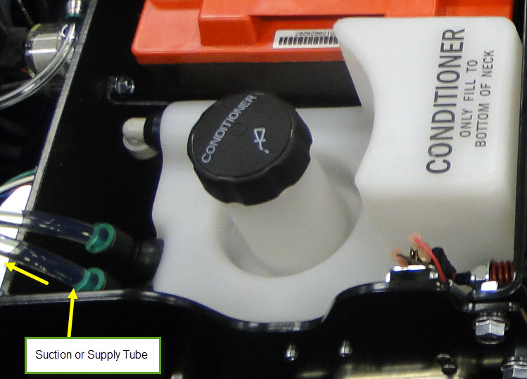
To start we need to de-pressurize and empty all the conditioner and cleaner from the conditioner and cleaner tanks.

See Section #6 Maintenance & Service
See Page # 130 for De-pressurizing the Conditioning System
See Page # 131 for Draining the Conditioner Supply Tank
See page # 126 for Draining the Cleaner Supply Tank


1. Remove the electrical enclosure from the machine.

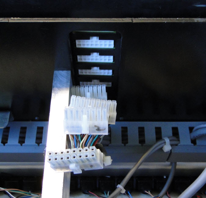
2. Disconnect all the connections from both RH and LH side of the electrical enclosure.

3. Remove the GUI, and then remove the injector cables that are below the GUI screen that route through the center wall off the machine. Mark these 1-5 so that they can be reinstalled the same as removed.


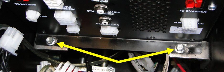
4. Remove the 4 each 3/8” socket head bolts that mount the electrical enclosure to the 4 “L” brackets.


5. You should be able to now lift the enclosure straight up and out of the machine and set aside.

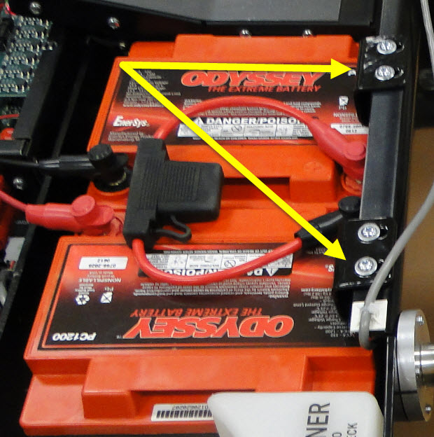
Next, we need to remove the battery and its tray.

6. Remove the two battery clamps.

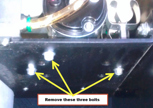
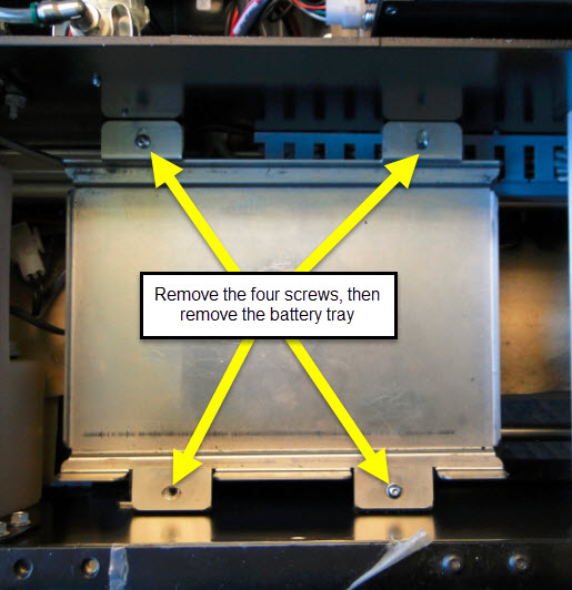
7. Remove the bottom battery tray. There are four hex cap screws holding securing this plate.


Now, we need to remove the conditioner tank.

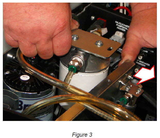
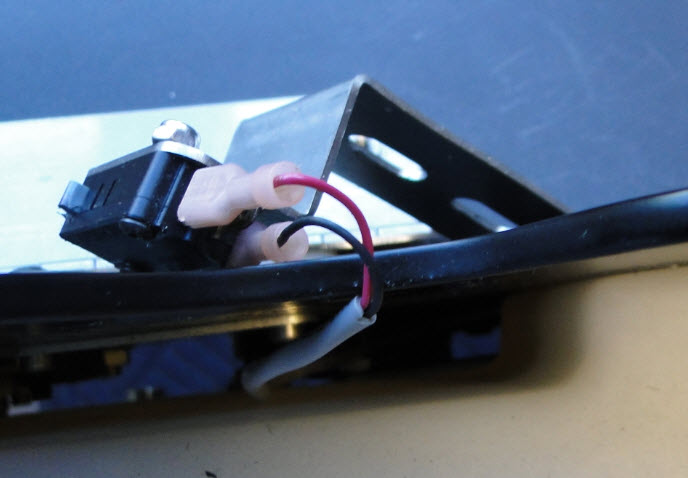
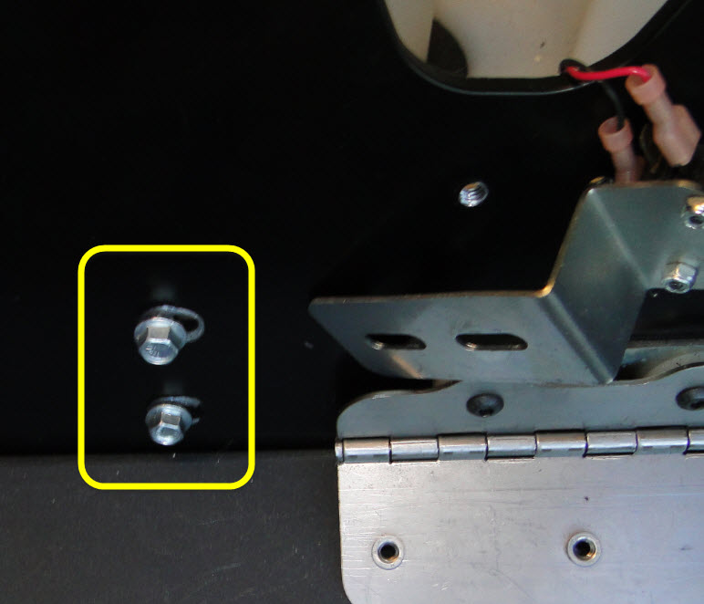
8. Remove the cord kill micro switch bracket by removing the two 3/8” bolts that mount the switch and lay the switch and bracket over the wall out of the way.


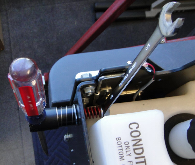
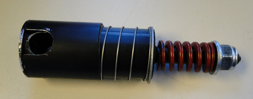
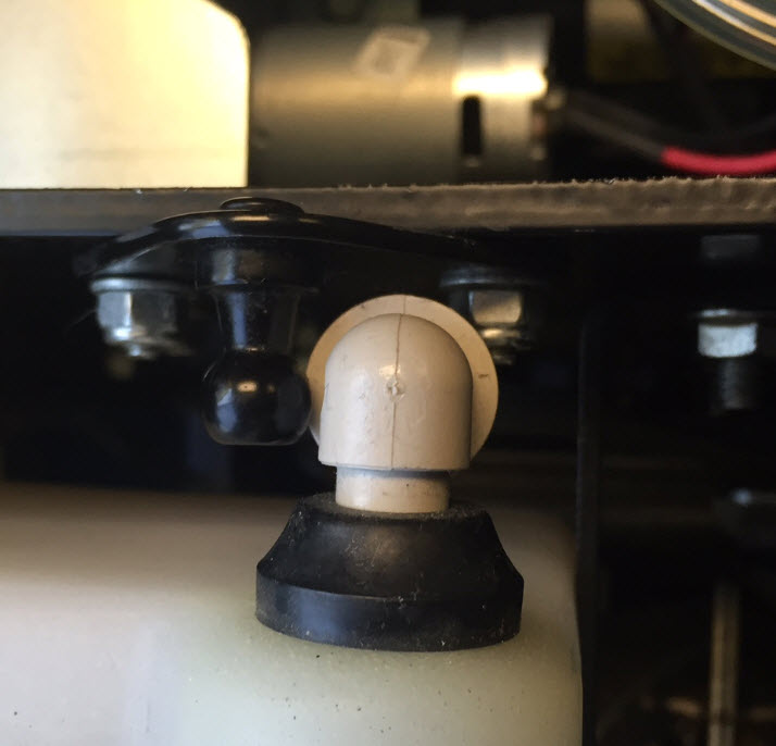
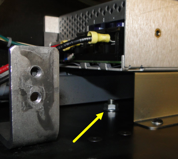
9. Remove the cord kill stud assembly. Use a large screwdriver to put in the slot where the cord ring would normally go. Then, using a 3/8” closed/open end wrench, start unscrewing the cord kill stud assembly and remove with the washers and spring. Place all parts back together.


10. Remove the gas spring shock at this location, take a small pocket screw driver and push the clip outwards to unsnap the shock from the ball.


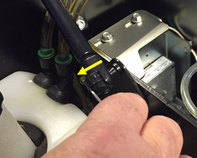
Note: Remember to de-pressurize the conditioning system and drain the system before you remove the hoses!

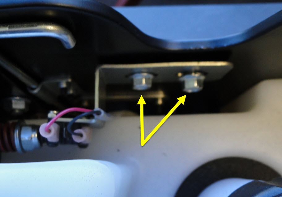
11. Find the two conditioner tank mounting bolts on the side of the machine and remove these. You will need to remove the side cover.


12. The tank is now loose and can be lifted straight up, but be careful of the air vent fitting towards the front of the machine. You can maneuver that fitting around the nut and ball joint of the hood spring. Just take your time.


13. Unplug the connection to the level sensor.

14. Lay the tank over to the side, or remove the tank by removing the two 3/8” hoses from the tank making sure you note where they came from. Then, take the 3/8” caps and cap off the both hoses so there are no leaks.


15. Remove the ¼” vent valve hose and cap.

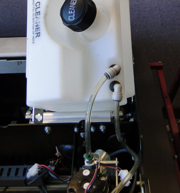
Next, we need to remove the cleaner tank.

16. Remove the two 3/8” socket head screws that mount the cleaner tank to the back wall.

17. Slowly lift the tank up and disconnect the level sensor connection.

18. Lay the tank over the side, or remove the tank by removing the two 3/8” tubes from the fittings and cap them off with 3/8” caps. Remember to drain the system and tank if you are removing the tank.


Before we remove the injector rail we will need to remove the injector connections from the injectors themselves.

19. Use a small pocket screwdriver or a paint can opener like in the tools picture, move the screwdriver between the injector and the felt padding centering the screwdriver to the injector.


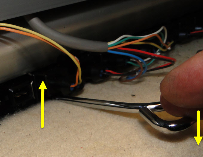
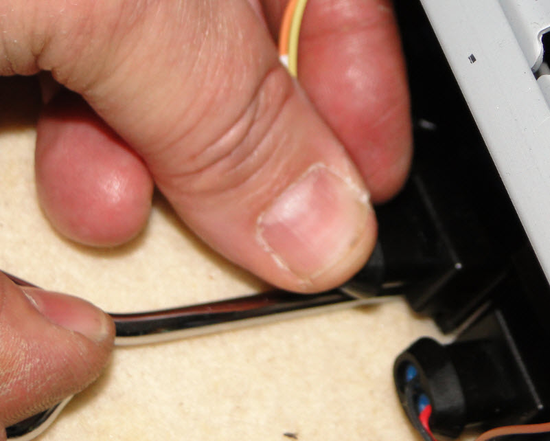
Then, push up on the screwdriver, this will push up on the clip on the injector unlocking it. While the injector is unlocked, grasp the connection and pull away from the body of the injector.


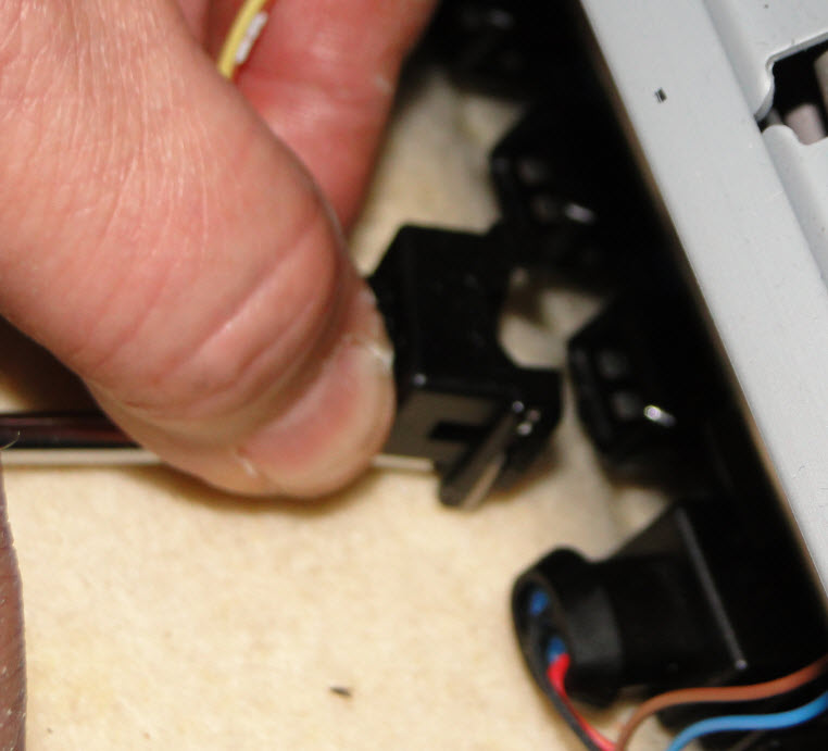
20. You will need to do this to all 39 injectors.

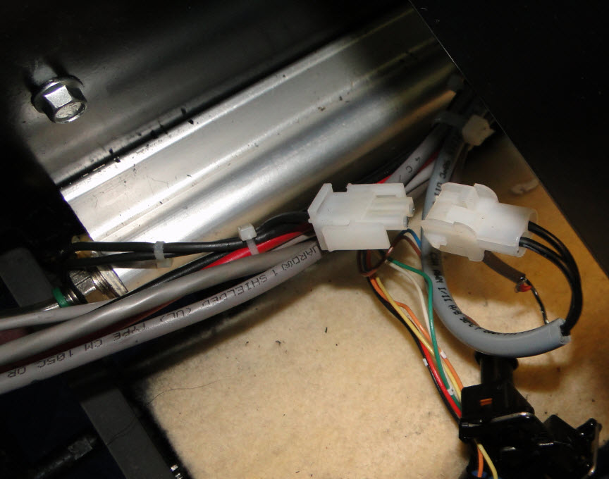
21. After you finish unplugging all 39 connections, disconnect the heater connection on the LH side of the injector rail under where the conditioner tank was mounted.


To get at the rail mounting nuts under the accumulator rail, you will need to remove the accumulator.
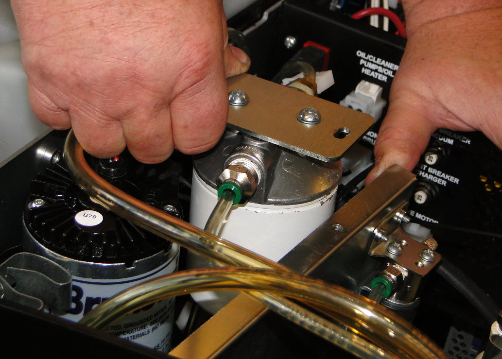
22. Remove the two mounting nuts and lift and move the accumulator away from the wall. Slide the two carriage bolts out and set aside as they may fall out and get lost.


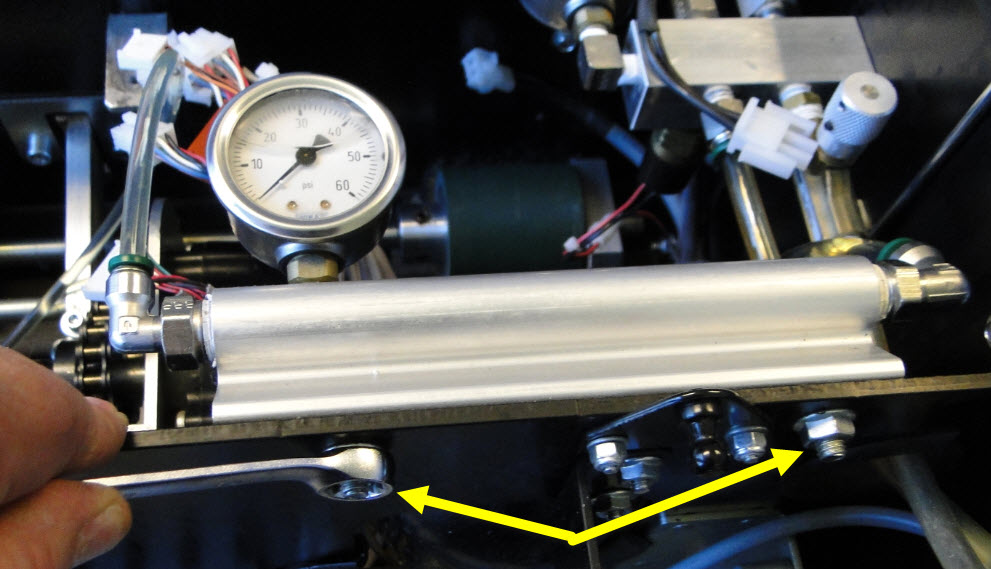
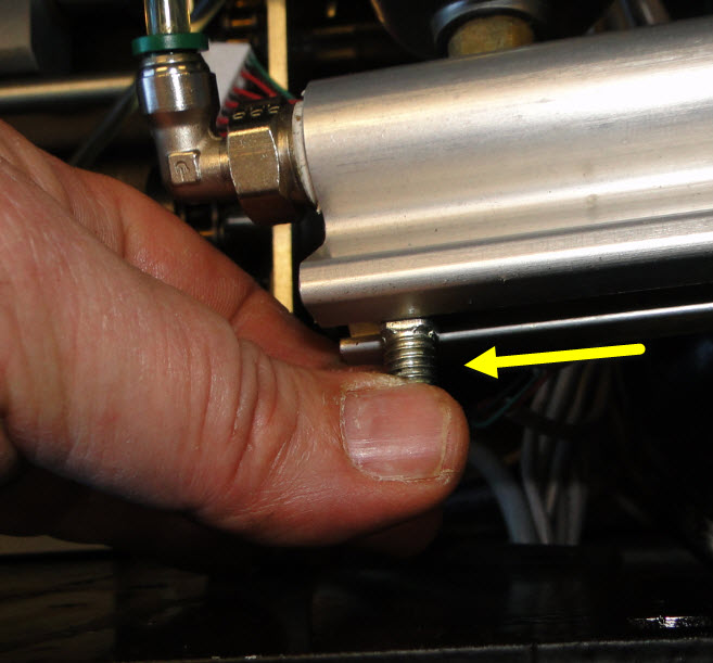
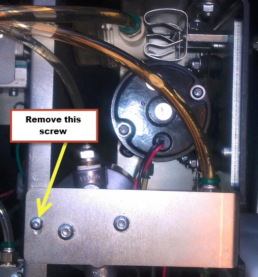
23. You should now have clearance to remove the two nuts for the injector rail.


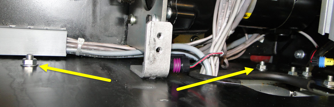
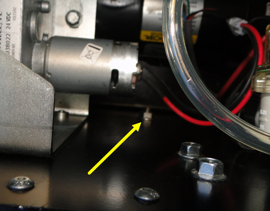
24. Remove the two other nuts along the rail on the inside so that the rail is loose. These are located below the buffer up/down motor and below the AC power converter.


Removing the rail:

25. Now that the rail is loose, you can disconnect the 1/4” or 3/8” hose that leads up to the spin on oil filter from the end of the injector rail on the left-hand side and remove the other 3/8” hose on the right-hand side that leads up to the accumulator rail.

26. Drop the injector rail out the bottom of the machine.

Once you have the old injector rail out you can now install the new rail by following these instructions in reverse.

Replacing the heater element in the injector rail:

By following the above replacement instructions, you will have the injector rail out of the machine. Now, you can work on this injector rail on the bench to replace the heating element.

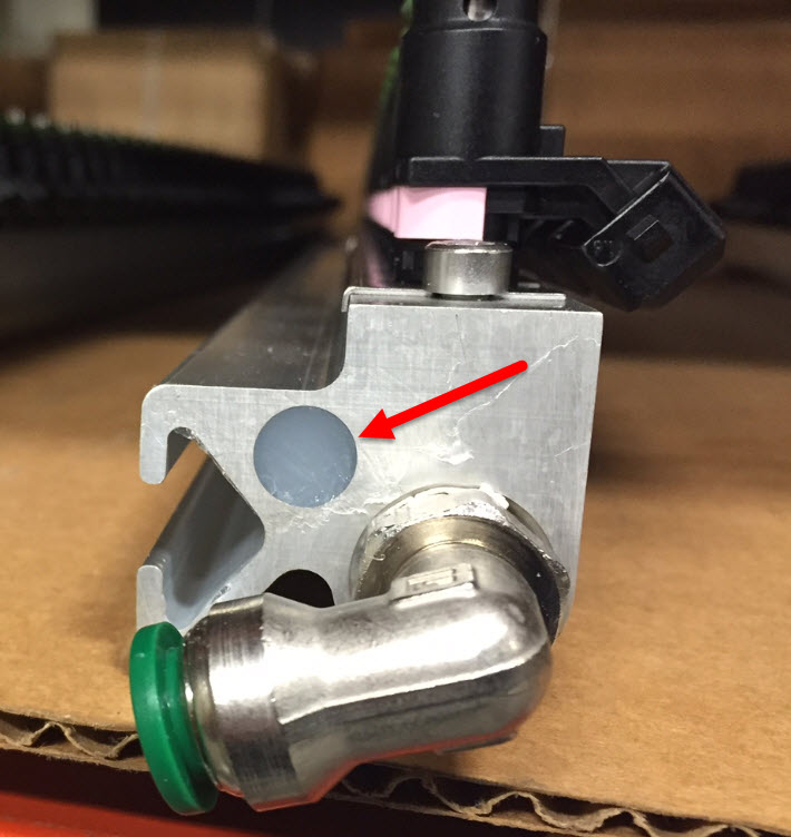
27. Remove all the silicone from each end of the rail that holds the element into the rail.


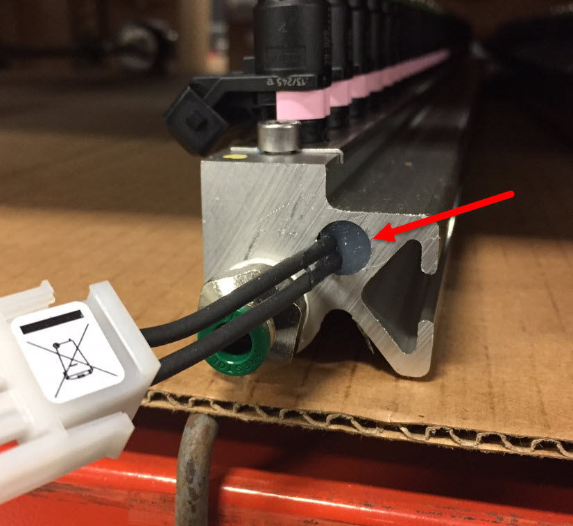
28. Pull out the heater element from the rail. If it does not want to come out easily, you may have to take a 1/4” threaded rod 20’ to 24” long to tap the element out of the injector rail.

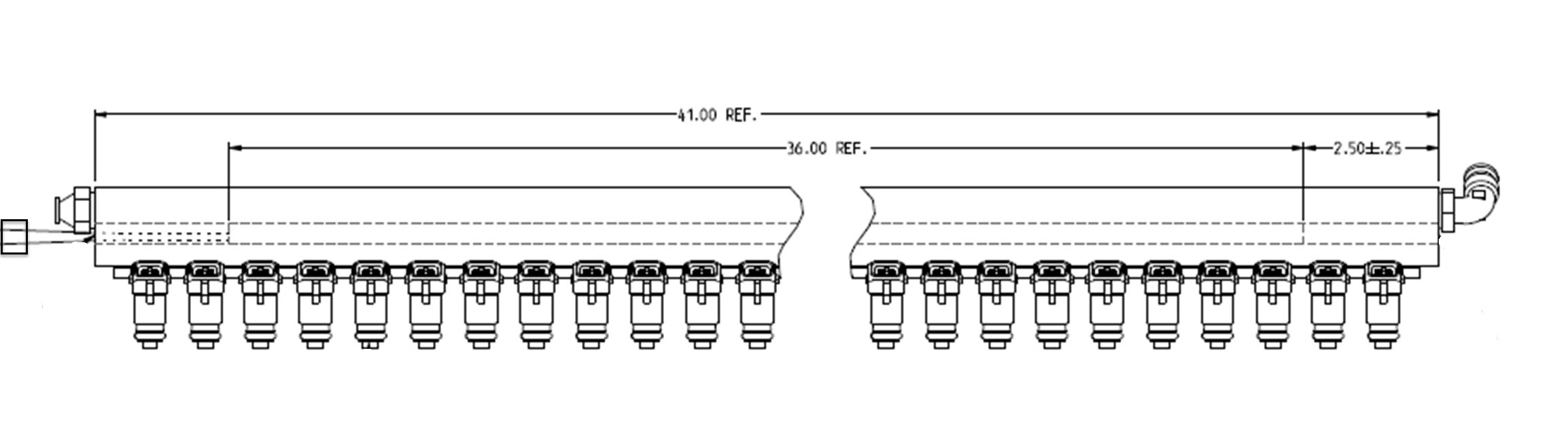
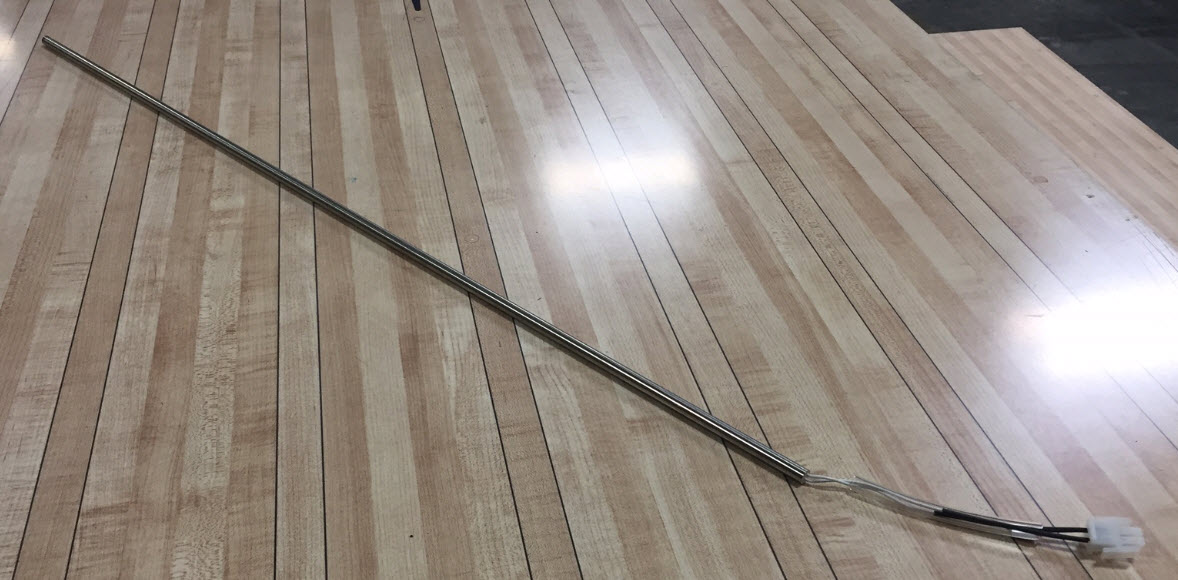
29. Once the heating element is out of the injector rail, install the new element into the rail trying to center it inside the rail. It should be placed 2-1/2” from each end. The rail is 41” long and the heating element is 36” long. Center it the best you can and then fill the cavity back up with silicone on both ends.


30. Reinstall the injector rail in reverse from the instructions above.

Applicable Files:
Related Information and Links:
Revision Date:
11/22/2016 - Released to KB

 
1.4. Matching Address of Replacement Transmitter w/Existing Remote Stop Receiver
Environment:
Lane conditioner machines
Applicable Version(s):
Envoy and Max lane conditioner machines
Procedure:
This procedure explains how to match the address of a replacement 14-100907-001 transmitter with existing remote stop receiver.
Applicable Files:
'14-100907-002rNC.pdf'
Related Information and Links:
Revision Date:
09/02/2022 - Released to KB

 
1.5. Max and Envoy Lane Machine Heater Troubleshooting Instructions
Environment:
Max or Envoy lane machine
Applicable Version(s):
All
Procedure:
See attachment
Applicable Files:
'Max and Envoy Lane Machine Heater Troubleshooting Instructions.pdf'
Related Information and Links:
Revision Date:
03/05/2020 - Released to KB

 
1.6. Process for Resolving Inconsistent Injections or Purging Contamination from the Conditioning System
Environment:
Envoy and Authority22 Lane Machines
Applicable Version(s):
All
Procedure:

PROCESS for RESOLVING INCONSISTENT INJECTIONS or PURGING CONTAMINATION from the Conditioning System

Note: Before starting on the following 12 or 23 step procedures, please read these “Suggestive Steps to Solve Inconsistent Injections”.  Try these first, and if issues persist, go to “Purging Contamination from the Conditioning System” below.

Suggestive Steps to Solve Inconsistent Injections:

Purging Contamination from the Conditioning System:

 Refer to pages 132-144 of the Envoy Operation & Service Manual (14-900101-000)

IF CLEANER IS ACCIDENTALLY ADDED TO THE CONDITIONER TANK BUT NOT CIRCULATED THROUGH THE SYSTEM:

DO NOT OPERATE THE MACHINE BEFORE CONDUCTING THE 14 STEP PROCEDURE below to contain the resulting white sludge from being spread through the rest of the conditioner system.  Conducting this procedure as soon as possible after the cleaner has been added to the conditioner tank will minimize the negative effects and avoid the need to conduct the 24-step process to purge the contamination from the complete conditioner system.

  1. Remove the pump outlet tubing at the compression fitting where it connects to the inlet of the Spin-On Oil Filter.

  2. Use union fitting to attach ~40” tubing (from spare parts kit or local hardware or plumbing store).

  3. Place loose end of this tube into a 2-5 liter container to collect the waste fluid.

  4. Go to the Diagnostics menu to activate the conditioner pump to pump all the fluid out of the conditioner tank.

  5. Remove conditioner tank to remove any solid or gel that remains in the bottom of the tank. Use IPA99 if necessary to help remove any contamination from inside the conditioner tank before reinstalling.

  6. Fill the conditioner tank with 99% Isopropyl Alcohol (61-860254-000/61-860254255-000 IPA 99) and purge any remaining conditioner/cleaner from the system tubing by activating the conditioner pump until the drain tubing in the waste container runs with CLEAR IPA 99.

  7. Clean or replace the conditioner screen filter. (page 137-138)

  8. Drain the Conditioning Supply Tank completely of all IPA 99. (pages 133-134)

  9. Fill the conditioner tank with the desired new Conditioner.

  10. Purge any remaining IPA 99 from the system tubing by activating the conditioner pump until the drain tubing in the waste container runs with CLEAR new Conditioner.

  11. Remove the drain tube and reconnect the tube onto the compression fitting where it connects to the inlet of the Spin-On Oil Filter.

  12. Replace the 11-655029-001 Spin-On Filter if necessary (pages 135-136). NEVER BYPASS the Spin-On Oil Filter when pumping fluid through the injector rail.

  13. With the machine in the operating position, turn on the heat cycle to circulate the new Conditioner in the system for a few minutes to purge air out of the system.

  14. Run the new Conditioner through the injectors by running a minimum of 5 lanes with the 100 Unit pattern for all 39 injectors for a single zone of 50 feet.

  • If the above procedure was not effective or if you are unsure if you contained the cleaner in the conditioning tank before it was spread to the rest of the system, you will need to conduct the 23-step procedure below:

IF CLEANER WAS CIRCULATED THROUGH THE SYSTEM or if the injectors are suspected of contamination USE THE BELOW PROCEDURE.

Please purchase 2 each 11-655029-001 Spin-On Filters for Replacement During this Procedure.

Parts needed: 

  • 2 Each 11-655029-001 Spin-On Filters
  • 6 Quarts IPA 99% alcohol (61-860254-000/61-860254255-000)
  • Teflon thread tape
  1. Completely Drain the old conditioner and residue from the Conditioning Supply Tank (pages 133-134). Pump out as much of the existing conditioner from the tank and system tubing as possible (+Physically remove conditioner tank to empty liquid or contamination below the inner tubing level.) BEFORE adding any IPA99.  If the 11-655029-001 Spin-On Oil Filter is completely plugged and blocking the outlet of the pump, it may be necessary to replace it with a new filter at this time instead of at step #7 (pages 135-136). NEVER BYPASS the Spin-On Oil Filter when pumping fluid through the injector rail. 
  2. Remove the accumulator from the accumulator rail and drain contents. Pour IPA 99 into the opening and fill to top. Shake the IPA 99 inside the accumulator to wash out any contaminates. Note: When replacing the accumulator, be sure to add Teflon tape to the threads of the fitting before reinstalling the accumulator.

  3. Fill the conditioner tank with 99% Isopropyl Alcohol (61-860254-000/61-860255-000 IPA 99).

  4. Purge any remaining conditioner from the system tubing by activating the conditioner pump until the drain tubing in the waste container runs with CLEAR IPA 99. 

  5. Remove the drain tube and reconnect the tube from the accumulator rail to the pressure control valve.

  6. Activate the conditioner pump to let the conditioner pressure increase to 45psi in the Diagnostics with the Oil Pressure Valve closed and then quickly turn the conditioner pump off.  Then open the Oil Pressure Valve to let the pressure drop to 0psi.  (This step helps purge residual conditioner that may be trapped in the accumulator).

  7. Replace Spin-On filter with new one.

  8. With the machine in the operating position, circulate the IPA 99 in the system for a few minutes to purge air out of the system (page 137).

  9. Remove the buffer brush (pages 143-144

  10. Create a special pattern that is 100 units of oil for all 39 injectors for a single zone of 50 feet.

  11. Run the IPA99 through the injectors by running a minimum of 10 lanes with this pattern.

  12. Drain the Conditioning Supply Tank (pages 133-134) by pumping out as much of the existing IPA99 from the tank and system tubing as possible.

  13. Fill the conditioner tank with the desired new conditioner.

  14. Purge any remaining IPA 99 from the system tubing by activating the conditioner pump until the drain tubing in the waste container runs with CLEAR new conditioner.

  15. Remove the drain tube and reconnect the tube from the accumulator rail to the pressure control valve.

  16. Activate the conditioner pump to let the conditioner pressure increase to 45psi in the Diagnostics with the Oil Pressure Valve closed and then quickly turn the conditioner pump off.  Then open the Oil Pressure Valve to let the pressure drop to 0psi. (This step helps purge residual IPA 99 that may be trapped in the accumulator).

  17. Replace the Spin-on Filter: Remove the spin-on filter that has residual conditioner and replace it with a new spin-on filter.

  18. With the machine in the operating position, turn on the heat cycle to circulate the new conditioner in the system for a few minutes to purge air out of the system.

  19. Run the new Conditioner through the injectors by running a minimum of 5 lanes with the 100 Unit pattern for all 39 injectors for a single zone of 50 feet.

  20. Run the Oil Injector Zig-Zag Test (pages 91-92) to assure that all injectors are properly firing with the expected pentagon shaped pattern.

  21. Reinstall the buffer brush. (pages 143-144)

  22. Select an actual pattern and run 10 lanes.

  23. Use the Computer Lane Monitor to assure that the oil volume is correct for the selected pattern.

If these steps do not clear the injectors, please contact Brunswick Tech Support for additional information techsupport@brunswickbowling.com or Domestic 231-725-4966 or International 231-725-4966

Revision Date:
12/05/2016 - Released to KB