1. Center Network Systems
1.1. 3rd Party Software
1.1.1. ELO Touchtool Drivers and Software
Environment:
Vector, Vector Plus, Sync CNS
Applicable Version(s):
Windows XP through Server 2012
Description:
Latest ELO Drivers for use.
Applicable Files:

EloDriver_Svr2008_5.8.0.exe

EloDriver_Svr2012,W10,W7,WXP_6.9.7.exe 

Related Information and Links:
N/A
Revision Date:
09/18/2017 - Released to KB.

 
1.1.2. Meriq Systems
1.1.2.1. Meriq Online Reservations
1.1.2.1.1. Configure Sync Deposit Accounts with Meriq Reservations
Environment:
Sync CNS with Meriq Online Reservations
Applicable Version(s):
Sync 3.8
Procedure:

This procedure is assuming Meriq has already connected to the system and configured Sync to interface with the Meriq reservation system online.

Create Account Category

  1. Open Sync Office
  2. Navigate to Analysis > Account Categories
  3. Click the + sign to create a new Category
  4. Name the category Online Reservations or something similar
  5. Click OK to save the new category
  6. Click Exit
Configure Online Reservation Deposits
  1. Open Sync Office
  2. Navigate to Sales > POS Policies
  3. Select the Reservations tab
  4. Click the drop-down for Default Online Deposit Collection type and Change to the one you created
  5. Click OK to save the change
At this point the system will automatically create deposit accounts for the Meriq reservations that are attached to the reservation.

The reservation deposits will be created with the reservation date and title from the reservation.  

Creating Payment Method

The next step is to create a payment method to allow for tracking of the incoming and outgoing funds.

  1. Open Sync Office
  2. Navigate to Sales > Cash Payment Methods
  3. Click the + sign to create a new payment method
  4. Name the method Online Deposits or something similar
  5. Check the Online Deposit Payment Method checkbox
  6. Click OK to Save the new payment method
  7. Click Exit
This will make sure all the sales reports properly account for the deposits coming into the system and being logged into the accounts. 
Applicable Files:
N/A
Related Information and Links:
N/A
Revision Date:
12/06/2022 - Released to KB.

 
1.2. Brunswick Sync
1.2.1. Sync Kiosk Scoring
1.2.1.1. Sync Kiosk Troubleshooting
1.2.1.1.1. Sync Kiosk Scoring - Customer Troubleshooting Guide
Environment:
Sync Scoring Kiosk Installations
Applicable Version(s):
Sync 3.7 and later
Document Description:
Comprehensive troubleshooting guide for end users.
Applicable Files:
Kiosk Scoring Troubleshooting - Customer.pdf
Related Information and Links:
N/A
Revision Date:
05/09/2022 - Released to KB.

 
1.2.1.2. Sync Kiosk User Manual
Environment:
Sync Kiosk system
Applicable Version(s):
Sync 2.2/2.3
Document Description:
This user manual describes how to bowl and navigate the screens necessary for the Sync Kiosk system.
Applicable Files:
Kiosk User Manual.pdf
Related Information and Links:
N/A
Revision Date:
05/16/2018 - Updated for Sync 2.2/2.3. Includes MyShot information.
01/19/2017 - Released to KB.

 
1.2.2. Sync Options
1.2.2.1. EPOS Interface
1.2.2.2. Sync Stored Value Interface
1.2.2.2.1. Stored Value - Reporting Information

Sync reports value added to stored value (SV) cards and value removed from SV cards via payments in the "Stored Value" section of the sales report. This section only includes direct addition/removal of monetary value to SV cards by Sync. It does not include SV package sales.

From the perspective of Sync, this operation directly adds or removes monetary value to/from a card. Therefore, these operations are not taxed because the SV card is functioning like a gift card, and sales of gift cards are not generally taxable nor do they count as revenue. If, however, adding a specified amount of money to a card from Sync "converts" the dollar amount to points/credits/etc. such that applicable laws and accounting rules dictate that this sale be reported as revenue and/or taxed, there are two options for the bowling center.

  • The first is to use SV packages to add value to cards - these are attached to products in Sync and these products can be taxed. 
  • The second is to account in the bowing center's accounting program for the value added to the cards. 
Note that in either case, if SV cards are allowed to be used as payment in Sync, the bowling center must be very careful to not count value added to SV cards as revenue/taxable sales and the products sold and paid for by SV cards as revenue/taxable sales or double-counting may occur.

1.3. Desk Peripherals
1.3.1. All in One COM Port Peripherals not Functioning
Environment:
All-in-One client computer
Applicable Version(s):
All-in-One pole display and receipt printer.
Issue:
Pole display or receipt printer do not work on All-in-One computer.
Cause:
No power is supplied to the COM ports used for All-in-one pole display and receipt printer causing failure to operate properly.
Solution:

You have to turn on +12V power to the COM port where the peripheral that requires power is using.  One example: Customer Display is plugged into COM 3 by default.

In order to power on the devices, you need to access the BIOS:

  1. Press the Delete button repeatedly during boot, after the POST beep and go to the Advanced tab. The boot up is fast so be prepared with pressing the Delete button.
  2. Select Intel Advanced Menu.
  3. Select the VGA/COM power Configuration and power ON the desired ports by selecting +12V (default is None). Please note, only turn power on for the COM port in which the peripheral requires power.
  4. Press the F10 button to save and exit the BIOS.

Warning!!!

The powered ports are designed strictly for Touch Dynamic products. Connecting peripherals other than TD rear LCD or 2x20 Customer Display to the powered port will result in the permanent system damage and will void the warranty!!! Do not disconnect or re-connect the devices to the ports while the system is up and running

Applicable Files:
Related Information and Links:
Revision Date:
05/26/2021 - Released to KB

 
1.4. Media Manager
1.4.1. Media Manager on Client Cannot Connect to Server
Environment:
Client computer with Media Manager installed
Applicable Version(s):
All
Issue:

The following error will show when trying to open the Media Manager application from a client computer:


Cause:
Possible Date/Time/Time Zone do not match the server.
Solution:

Ensure all date/time/time zone of the client match that of the server exactly.

The command: net time \\cmserver /set may be run from the client computer in a command prompt window to match the server time exactly. Just answer "Y" to the question that presents after running the command if the time from the server is correct and you want to accept the time match.

Applicable Files:
Related Information and Links:
1.4.2. Media Manager Video Learning
Environment:
Vector Plus/Vector with Media Manager
Applicable Version(s):
All
Document Description:

The zip file contains flash-driven video tutorials on using the Brunswick Media Manager.

Users should start with the Media Manager Main Menu.exe file.

Applicable Files:
MediaManagerVLTs.zip
Related Information and Links:
Download File
Revision Date:
08/20/2016 - Released to Knowledge base.

 
1.5. Vector Desk Control
1.5.1. Locked Transaction(s) in Vector Desk
Environment:
Vector Desk
Applicable Version(s):
All
Issue:
Cannot cash out a lane, or if you select it, it locks the reception payment screen up.
Cause:
There is a locked transaction in the database.
Solution:

1. Insert your Vector disk.

2. Navigate to 6433 Folder on Vector Disk.

3. Run FixTrans.exe.  

Applicable Files:
See attachment
Related Information and Links:

Revision Date:
4/15/16

 
1.5.2. Vector Desk Control and Irfanview Commercial Creation
 
Title: Vector Desk Control and Irfanview Commercial Creation
Environment: Vector scoring
Applicable Version(s): All
Description: How to edit Commercial files using the Irfanview program
Applicable Files: See attachment
Related Information and Links:
1.6. Vector Plus
1.6.1. VP Export Utility
Environment:
Vector Plus locations
Applicable Version(s):
Documentation is based on VP version 7.0.7
Document Description:
User guide and data field explainations
Applicable Files:

VP Journal Log Export Field Descriptions.docx

VPExport User Guide.docx

Related Information and Links:
N/A
Revision Date:
05/14/2022 - Released to KB.

 
1.6.2. VP Mechanic
1.6.2.1. Cash Drawer Will Not Open but Receipt Printer Works
Environment:
Serial port settings for cash system
Applicable Version(s):
All
Issue:
Cash drawer won't open, but pole display and receipt printer may function normally.
Cause:

The check box for the CMS compatible option may be selected indicating legacy cash peripheral hardware, but the peripherals are not legacy.

Legacy hardware includes Star printers, intelligent cash drawers, and beige colored customer displays (pole display).

Solution:
Remove the check mark for CMS Compatible. Only check the CMS compatibility box for legacy pole displays, receipt printers, and cash drawers.
Applicable Files:

Related Information and Links:

Revision Date:
3/10/2016

 
1.6.3. VP Office
1.6.3.1. Daily Reports Automatic Email Option Fails to Send Email
Environment:
VP Office > Daily Reports
Applicable Version(s):
6.629 and higher
Issue:
The email for the Daily Reports is not sending properly.
Cause:

Either lack of Internet connection on the server, lack of repository folder for .pdf report or a configuration setting in VP Office > Daily Reports is incorrect. Typically, the SMTP, Port assignment or SSL designation is incorrect.

 
Solution:

Ensure all required fields of the Daily Reports section are filled in with correct and working information. The attached document describes all required fields and explains how to use the Daily Reports feature.

The following information can be utilized in the Email Settings section to test and validate that the Daily Reports is working properly:

SMTP Host: smtp.gmail.com
Sent email address: brunswick.tester@gmail.com
Email password: brun5w1ck
Port: 465
SSL: checked


Applicable Files:
'Automatic Daily Reports.pdf'
Related Information and Links:
Revision Date:
09/19/2018 - Released to KB

 
1.6.3.2. Microsoft .NET Framework unhandled exception error logging into Office from any client or server.
 
Title: Microsoft .NET Framework unhandled exception error logging into Office from any client or server.
Environment: Vector Plus CNS System
Applicable Version(s): This tip applies to Vector Plus version 5.xxx
Issue:
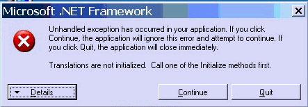
 The following error shows when logging into Vector Plus Office from any client or server.

Cause: The c:\CM2\Translations\CMEnglish.mdb file is corrupted.
Solution: Copy the c:\CM2\Translations\CMEnglish.mdb from the Vector Plus version 5.xx update cd to the  c:\CM2\Translations folder.
Applicable Files:
Related Information and Links:
1.6.4. VP Options
1.6.4.1. VP Ticket Depot
1.6.4.1.1. Ticket Depot does not Dispense Tickets
 
Title: Ticket Depot does not Dispense Tickets
Environment: VP Desk
Applicable Version(s): VP with Ticket Depot (VP 5.124 and newer)
Issue: Ticket Depot units will not dispense tickets nor automatically disable after a game
Cause: This means the Ticket Depot units are not receiving any Vector Notification messages.
Solution:

Verify that the Ticket Depot option CD has installed in the center by checking the server for a service called "Brunswick Ticket Depot Service". Next, check that the Ticket Depot feature is activated in Site Management. If the service is present on the server but the feature is deactivated in Site Management, follow the steps below. Otherwise, you have not run into the issue that this solution solves.

If the feature should be activated, activate it via Site Management.

If the feature should not be activated, disable the "Brunswick Ticket Depot Service".
Applicable Files:
Related Information and Links:
1.6.4.1.2. Ticket Depot Installation and Vector Plus Users Guide
Environment:
Ball lift area and Vector Plus CNS system
Applicable Version(s):
Vector Plus 5.104 and higher with Vector Scoring
Document Description:
These documents describe the Ticket Depot system installation and use.
Applicable Files:

'Ticket Depot Installation 57-900080 - 1-14.pdf'

'Ticket Depot_Vector Plus User Guide.pdf'

Related Information and Links:
Revision Date:
09/06/2019 - Released to KB

 
1.6.5. VP User Guides
2. Lane Maintenance
2.1. Brunswick Envoy
2.1.1. Graphical User Interface (GUI) Envoy
2.1.1.1. Making a Back Up File for the Envoy Lane Machine
Environment:
Envoy Lane Machine Graphic User Interface Pattern and Settings
Applicable Version(s):
All
Procedure:

Making a backup file for the Envoy Lane Machine

1. Make sure the Graphic User Interface (GUI) is at the operator’s screen. (see Figure #1)

Figure #1   


2. Insert Thumb Drive (Flash Drive) into the USB port on the left hand side of the GUI. (see Figure #2)

Note: Make sure you use an empty Thumb Drive / Flash Drive with no folders or files on it. Leaving other lane machine “backup” folders on a thumb drive may cause inadvertent installation of another centers lane machines settings.

Figure #2


3. The “Import Data / Export Data” screen will appear. Default is “Export Data” Press the green “Okay” to proceed to the next screen. (see Figure #3)

Figure #3


4. Now you are at the "Export Data" screen, press the green “Okay” button one more time. (see Figure #4)

Figure #4

5. You will see this screen for a few seconds, the words will be missing but it is okay, then the “Import Data” / “Export Data” screen the words come back. At this time, you can remove the Flash drive / Thumb Drive from the GUI. This part is now done. You now have a folder on your thumb drive called "backup" this folder will have all your patterns and settings data. (see Figure #5)

Figure #5


Finding and sending the “backup” file in email.

Insert your “Thumb Drive / Flash Drive” into your personal computer. Open your drive and look for a folder called “backup”.


Double click on this “backup” folder to open it. You should see some files listed in this folder. Scroll down to the bottom of this folder and there will be a zipped folder called “backup.1.zip”. This is the folder that we will need sent to us for troubleshooting.


Send this “backup.1.zip” folder to techsupport@brunswickbowling.com and add in the subject line the reference number in the email we have been corresponding. Example is below.


Note: Always store the centers backup files in a folder designated for that center and date it, leaving “backup” folders on your thumb drive may lead to loading some other centers pattern and settings inadvertently being loaded into another centers lane machine. All Authority22 and Envoy lane machine back up folders are called “backup” so they need to be filed away and separated.

Revision Date:
3/6/2017 - Released to KB

 
2.2. Incorrect Pressure Readings or No High Conditioner Pressure Warning
Environment:
Conditioner pressure sensor and GUI
Applicable Version(s):
All Versions A22 and Envoy lane machines
Issue:
Incorrect pressure readings or no high conditioner pressure warning.
Cause:
Bad Conditioner pressure sensor and/or bad conditioner pressure cable connections.
Solution:
See attachment
Applicable Files:
'Incorrect Pressure Readings or No High Conditioner Pressure Warning.pdf'
Revision Date:
09/26/2018 - Released to KB

 
2.3. Low or High Pressure Errors on Brunswick Lane Machines
Environment:
Brunswick Lane Machines (A-22, Envoy, MAX)
Applicable Version(s):
All
Issue:
Inconsistent conditioner volume, low or high-pressure errors.
Cause:
The pressure for the Accumulator Diaphragm is at or below 10 PSI.
Solution:

In order to properly diagnose this issue, we we will need to remove the accumulator diaphragm to verify the PSI.

When accumulator is completely low on PSI the Gauge needle will jump from approximately 25 PSI to up to 60 PSI. Triggering a High-pressure error.

Procedure to Remove and Verify Pressure


  1. Disconnect wires connection from the Pressure sensor and temperature sensor from the accumulator rail.
  2. Remove the two ½ inch nuts that holds the accumulator rail assembly.
  3. Turn the Accumulator rail in a vertical position. Remove the hex cap to expose the stem valve.
  4. Check the accumulator pressure using a tire pressure gauge. Should read 10 to 10.5 PSI.
  5. If the pressure is below 10 PSI you will need to inflate the accumulator bladder using a bicycle air pump. If you exceed 10 PSI, simply push the stem valve very quick to deflate until you reach 10 to 10.5 PSI.
  6. Once completed re install the accumulator rail and reconnect the pressure and temperature sensors.


Applicable Files:
N/A
Related Information and Links:
N/A
Revision Date:

08/25/2020 - Revised document to web format.
09/17/2018 - Released to KB


3. Pinsetters
3.1. Brunswick GS
3.1.1. Brunswick GS-X Pinsetters
3.1.1.1. Nexgen Electronics
3.1.1.1.1. GSX Nexgen Keypad is Unresponsive
Environment:
GSX Nexgen Electronics
Applicable Version(s):
All
Issue:
The Nexgen keypad is unresponsive
Cause:
The Reset Button is stuck at the ball rack or there is a shorted wire from the Nexgen cable to connectors P4 and P20.
Solution:
See attachment
Applicable Files:
"Nexgen Keypad NonResponsive.pdf"
Related Information and Links:
Revision Date:
08/16/2018 - Released to KB

 
3.1.1.1.2. Functional Test Codes Appear on Nexgen Display After Installing CPU
 
Title: Functional Test Codes Appear on Nexgen Display After Installing CPU
Environment: GS-X Pinsetter with Nexgen Box   
Applicable Version(s): All Nexgen Boxes
Description: Locate and remove the test jumper labeled J7 on the CPU Board. This is located just under and to the left of the F3 fuse location. This will usually occur when a customer receives a CPU PCB that has been repaired by the Electronic Repair Center and the jumper has been left on from testing.
Applicable Files:
Related Information and Links:
3.1.1.1.3. Unable To Scroll Through Modes On Nexgen Box Display Using Keypad
 
Title: Unable To Scroll Through Modes On The Nexgen Box Display
Environment: Nexgen GUI display
Applicable Version(s):
Issue: Unable to scroll through modes of the Nexgen box display using the keypad.
Cause: Reset button or buttons at the ball rack in the bowlers area are stuck in the engaged position (Frameworx ball lifts with oval style reset buttons).
Solution: Dis-engage the reset button or buttons at the ball rack in the bowlers area.
Applicable Files:
Related Information and Links:
3.1.1.2. Setting Table
3.1.1.2.1. Pin Gripper Quick Release Procedure
Environment:
GS Setting Table
Applicable Version(s):
GS- pinsetters with black pin holders only.
Procedure:
This procedure describes how to remove the Pin Gripper from a Pin Holder without removing it from the setting table.
Applicable Files:
'Pin Gripper Quick Release Procedure.pdf'
Related Information and Links:
Revision Date:
01/03/2019 - Released to KB

 
3.1.1.3. Sweep Wagon
3.1.1.3.1. Sweep Release Adjustment
Environment:
GS-X pinsetter sweep wagon
Applicable Version(s):
All
Procedure:
See attachment
Applicable Files:
'Sweep Release Adjustment.pdf'
Related Information and Links:
Revision Date:
09/19/2018 - Released to KB

 
3.1.1.3.2. Troubleshooting 75 Error Code with GSX Pinsetter
Environment:
Nexgen box
Applicable Version(s):
All
Issue:
Pinsetter has displayed an error code 75
Cause:
The error code 75 is displayed if the pinsetter does not recognize that the sweep has dropped to the guard position.
Solution:
See attachment
Applicable Files:
'Troubleshooting Code 75 Error on GSX Pinsetters.pdf'
Related Information and Links:
Revision Date:
09/28/2018 - Released to KB

 
3.1.2. How To Locate the Nexgen Box Firmware Version
Environment:
GS Nexgen Box
Applicable Version(s):
All
Procedure:
There are two ways to locate the firmware version. (This only applies to Nexgen Electronics)
  • Turn the main Nexgen Power Switch to the "OFF" position and then back to the ON position and wait for the display to boot up on the Nexgen Box. If a PF code appears then turn the RUN / Stop Switches Off and back On again to clear the PF codes.The firmware version will then be displayed.

If the PF code is not enabled the display will show the firmware version.

  • With power applied to the Nexgen Box. Switch both Run / Stop Switches to the "OFF" Position. Press the " Mode" key repeatedly until "Setup" appears on the display / Press the "Enter" key one time and the Nexgen Firmware version will be displayed.
Applicable Files:
Related Information and Links:
Revision Date:
12/7/2017 - Released to KB

 
3.2. Brunswick Model A
3.2.1. Brunswick A2 Pinsetters
3.2.1.1. Electrical
3.2.1.1.1. A Lane Scores the Ball Thrown on the Pairs Opposite Lane
Environment:
Distribution board v5.0 and v6.0
Applicable Version(s):
All   
Issue:

One of the following occurs:


  • Single Lane: Either Lane assignment: Sweep drops and machine will not score on automatic trigger.
  • Lane Pair: One lane sweep drops and no scoring or triggering. Second lane drops the sweep and scores, and both cycle continuously.
  • Left pinsetter drops sweep and right lane cycles continuously after first ball.


Cause:

The Sweep Switch wiring is incorrect or reversed at the distribution board connections J1 Left and J2 Right.

Solution:

A. Ensure that the correct sweep switch cable from the pinsetter representing the odd and even lane is plugged into the proper odd/even lane ports J1 and J2 of the Distribution board.

  1. Turn on both lanes with sweep up.
  2. Remove distribution board cover.
  3. Power off both lanes.
  4. Manually drop either rake to confirm if the correct LED lights up for the lane that you dropped the sweep on.
  • On a V6.0 Dist. board, expect lights at LEDs: 

            D20 indicates when the right sweep is down.

            D26 indicates when the left sweep is down.

The below image is an example of a V6.0 Distribution board:


  • On a V5.0 Dist. board, expect lights at LEDs:

            D12 indicates when the right sweep is down.

            D14 indicates when the left sweep is down.

Applicable Files:
Related Information and Links:

Revision Date:

12/6/2017 - Released to KB

12/8/2017 - Updated image and text 


3.2.1.1.2. A-2 Low Voltage Electrical Trouble Shooting Schematic
 
Title: A-2 Low Voltage Trouble Shooting Wiring Diagram
Environment: A-2 Pinsetter
Applicable Version(s): All
Description:
Applicable Files:
Related Information and Links:
3.2.1.1.3. How to Jump the Manager and Masking Unit Cannon Plugs


Title:

Jumping the Manager and Masking Unit Cannon Plugs

Environment: A2 Pinsetter
Applicable Version(s): All
Description:

Remove the 3 pin and 5 pin cannon plugs located at the top of the Electrical Box.

- To jump the masking unit switch if equipped. Use a jumper wire between the B and C locations on the 3 pin cannon plug receptacle.

- To jump the managers control signal jump the A and B positions of the 5 pin cannon plug receptacle.

3.2.1.2. Elevator Assembly
3.2.1.2.1. Ball Lift Rod Clapper Box Adjustment Screw Modification
 
 
Environment: Elevator Ball Lift Clapper Box
Applicable Version(s): All
Procedure: Ball Lift Rod Adjustment Screw Modification
Applicable Files: 'Clapper_Box_Adjustment.pdf'
3.2.1.2.2. Ball Wheel Belt Removal and Replacement
 
Environment: A/A2 pinsetters
Applicable Version(s): All

Procedure:

1. Disconnect power cord and turn off circuit breaker on the electrical box.

2. Remove back Elevator Guard index E 45 page 143.

3. Remove Belts from the pinsetter motor to gear box belts and motor to elevator belts.

4. Remove tension spring E 8 page 141 and long turret belt index E 3 page 139 and cross conveyor drive belt E 4 page 139.

5. Remove idler tension for ball wheel belt by pushing up on the idler assembly index E 31 page 143 and remove ball wheel belt from under the pulley.

6. Remove idler assembly index E 31 page 143 by removing both hex head screws index E 80 page 143 from the shaft index E 32 on page 143 and remove ball wheel belt idler.

7. Remove hex head screws index E 18 A from inside bracket index E 18 K on page 141.

8. Remove pit conveyor idler assembly by removing screw index PC 6 page 79.

9. Remove left hand wheel guard by Index E 57 page 143 by removing both mounting screws index E 150 and index 117 A page 143 and remove guard.

10. Loosen ball wheel guide rollers on the left and right side of the ball wheel by loosening nuts on the guide roller arms index E 130 and index E 134 on page 145. Loosen the screws just enough to raise the arms up off the ball wheel.

11. Lift the ball wheel index E 142 page 145 and remove ball wheel belt from the under side of the ball wheel and just let it lay on pit carpet.

12. Push ball wheel belt up between bracket index E 18 K and elevator frame, move belt up and over the sheave index E 39 on page 143 and let it lay over the cross conveyor assembly.

13. Unplug pinsetter motor and remove hex head screw index E 83 and nut index E 99 from the motor mount index E 116 on page 147. Take the ball wheel belt and pass around the pinsetter motor towards the front of the pinsetter and send it between the motor mount index E 116 and frame of the pinsetter.

14. The belt should now just be hanging over the top of the turn pan and cross conveyor.

15. Remove turn pan spring index CC 4 Page 86 that holds turn pan to the cross conveyor frame.

16. Remove nuts index CC 14 from J bolts CC 15 page 89.

17. You will have to now pass the belt through the return track assembly by removing nuts index 12 page 189 and cap screw index 39 page 189 from track index 1 page for the even numbered pinsetter and remove index 12 page 189 and cap screw from the track index 2 page 189 for the odd machine, you will also have to remove the index 3 page 189 from the ball joint index 36 page 189.

18. Remove ball wheel belt.

19. Reverse procedure for reinstalling new belt.

Applicable Files:
Related Information and Links:
3.2.1.3. Gear Box
3.2.1.3.1. Clutch Reset Lever Replacement
 
Environment: A and A2 Pinsetter
Applicable Version(s): A and A2 Pinsetters
Procedure: This procedure will allow for quick removal and replacement of the Clutch Reset Lever. The procedure also eliminates the need to use a hammer and a punch to remove the lever.
Applicable Files: 'Clutch_Reset_Lever_Replacement.pdf'
3.2.1.4. Turret Assembly
 
Title:
Environment:
Applicable Version(s):
Description:
Applicable Files:
Related Information and Links:
3.2.1.4.1. How To Tell If A Short Turret Belt Is Stretched
 
Environment: A / A-2 Pinsetter
Applicable Version(s): All
Procedure: See attachment
Applicable Files: 'Stretched_Short_Turret_Belt_Test.pdf'
3.3. Brunswick String
3.3.1. 5-Pin String Machine Scores All Strikes or All Gutters
Title: 5-Pin String Machine Scores All Strikes or All Gutters
Environment: 5-Pin String Machine
Applicable Version(s): All
Issue: All balls thrown are scoring either strikes or gutters.
Cause:

A faulty B2 PCB, a faulty cable going to or coming from the B2 PCB, or a disconnected cable connection and/or soldered connection between the B2 PCB and the pinsetter interface box.


Solution: Ensure that the B2 PCB is functioning, the cables coming from and going to the B2 PCB are good, and all soldered connections are solid.
Applicable Files:
Related Information and Links:
3.3.2. Brunswick Stringpin 360v2
3.3.3. Modify 360 String Pinsetters with New Style Pit Curtain to Allow for Light Bowling
Environment:
String Pinsetter
Applicable Version(s):
All
Procedure:
See attachment
Applicable Files:
'Modify 360 String Pinsetters with New Style Pit Curtain to Allow for Light Bowling.pdf'
Related Information and Links:
Revision Date:
12/11/2018 - Released to KB

 
3.3.4. No Score is Posted on a Lane While Pinsetters Function Normal
Environment:
360 Controller of string pin pinsetter
Applicable Version(s):
All
Issue:
The lane is not posting a score when a ball is thrown even though the pinsetter functions as normal.
Cause:
The lane could be in one of the stand alone mode options.
Solution:

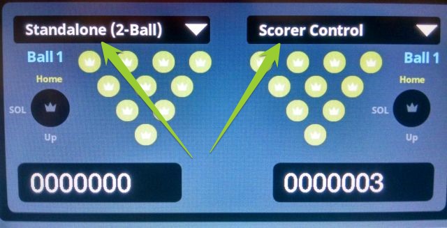
When viewing the 360 Controller LED display on the pinsetter rear, you should see both pinsetters listed in "Scorer Control".

The left lane is in "Standalone (2-Ball)" mode and the right lane is in "Scorer Control" mode.

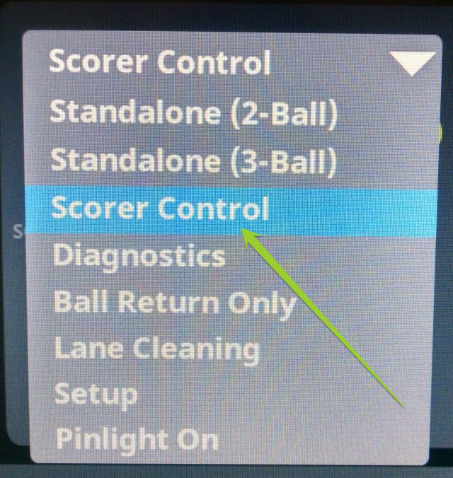
If the lane is in a certain stand alone mode and there are scoring or control issues on those pinsetters, change the pinsetter to "Scorer Control" mode by:

1. Turning off the pinsetter with the on/off switch to the right of the display for that pinsetter.

2. Pressing the drop down arrow for the mode option and select the mode desired, such as 'Scorer Control'.


3. Turn the pinsetter back on with the on/off switch to the right of the display for that pinsetter.

It should now display the "Scorer Control" mode and should score properly while interfaced with the scoring system. 

Applicable Files:
Related Information and Links:
Revision Date:
3/31/2017 - Released to KB

 
3.3.5. No Score or Abnormal Score Delay up to 20 Seconds
 
Environment:
5-Pin Vector ball detects
Applicable Version(s):
Model CA-1 5-Pin Interface
Issue:
5-Pin lane will not score at times. Or, the scoring is delayed up to 20 seconds.
Cause:
Ball detects are not adjusted properly
Solution:
Ensure that the 5-pin Vector ball detects are perfectly adjusted.
Applicable Files:
Related Information and Links:
3.3.6. One or More Pins Constantly Score Standing
Environment:
5 or 10 String pin machine
Applicable Version(s):
All with 360 controller. Other models might present similar or additional symptoms such as constant cycling.
Issue:
One or more pins will constantly score as it is standing no matter what combination of pins are knocked down. There may also be constant cycling involved.
Causes:
  1. One cause related to this issue was a washer that was stuck to the sensor magnet. The magnet was holding the washer in a position that blocked proper sensor scoring.
  2. The magnet gets restricted and stuck against the reed switch.
Solution:
Always ensure there are no loose parts in and around the string pinsetter area, as well as no small washers, screws or foreign objects stuck to the magnets or blocking the sensors. 
Revision Date:


3.3.7. String Pin Pinsetter Constantly Cycles
Environment:
Pinsetter
Applicable Version(s):
360 String Pin Pinsetter V1/V2
Issue:
360 Pinsetter constantly cycles up and down.
Cause:
  1. Ball detect is misaligned and/or damaged.
  2. Strings on top of the pins are so tangled they cannot be automatically untangled by the pinsetter.
  3. The blue reset button is stuck in.
Solution:
  1. Align bell detect properly and replace if necessary.
  2. Power down the pinsetter and manually untangle the strings for the pins.
  3. tap or press the blue button until it dislodges from being stuck.
Revision Date:
03/10/2023 - Released to KB

 
3.3.8. String Pin Settings
Environment:
Sync, Vector Plus & Vector with String Pin installed
Applicable Version(s):
All
Applicable Files:
String Pin Settings
Revision Date:
04/26/2016 - Released to KB

 
3.3.8.1. How to Change Modes for 5 and 10 pin Bowling with 360 Controller
Environment:
String Pin 360 Controller
Applicable Version(s):
All
Procedure:
See attachment
Applicable Files:
'How to Change Modes for 5 and 10 pin Bowling with 360 Controller.pdf'
Related Information and Links:
Revision Date:
12/10/2018 - Released to KB

 
3.3.8.2. String Pin Error Codes in Sync Peripheral Log Report
Environment:
Display Controller - C:\Program Files\Brunswick\Sync\SyncInstall\Configuration\Processes\Peripheral Manager\Logs
Applicable Version(s):
All String Pin Pinsetters and Sync
Document Description:

String Machine Errors:

00   Power on (3 phase power)
01   Tangle
02   Motor Backwards
03   Ball Accelerator Overload
04   Motor Overload
05   Pins Up Switch Expected
06   Pins Up Switch Not Expected
07   Pin Solenoid Switch Expected
08   Pin Solenoid Switch Not Expected
09   Home Switch Expected
10   Home Switch Not Expected

0b0c Power Cycled to 360 controller 


Revision Date:
12/22/2017 - Released to KB

 
3.3.8.3. String Pinsetter Initial Setup and Adjustments Instructions
Environment:
String Pinsetter
Applicable Version(s):
All with 360 Controller
Procedure:
See attachment
Applicable Files:

'String Pinsetter Initial Setup and Adjustments Instructions.pdf'

'String Pin Adjusting.pdf' 

Related Information and Links:
Revision Date:
11/13/2018 - Released to KB

 
3.3.9. String Pin will not Turn on when Lane Issued by Sync
Environment:
String Pin pinsetter 360 Control Box
Applicable Version(s):
All Sync with 360 Control Box software version less than 1.1.22
Issue:

The following items will occur indicating a 360 Control Box lock up(freeze).

  • String Pin pinsetter does not turn on when the lane is issued from the Sync system.
  • The 360 Control Box GUI will not display the options from the drop down box.

  • The heart beat LED on the 360 Control Box Slide-Out PCB will either be steady RED or OFF, and it is not blinking as a heartbeat.

  • There will be no pinsetter or pin deck lighting control from Sync desk.
Cause:
This seems to be the case when the system is not used, but still left running for a certain period of time. Although, the exact period of time the system is not used in order to cause this issue is unknown. However, it seems to be more prevalent in the residence installations where the system is more likely to be dormant for longer periods of time than an actual business that runs the strings pin pinsetters daily. We have seen this issue happen within 2 days of no use.
Solution:

The 360 Control Box Slide-Out PCB must have its firmware updated to minimum version 1.1.22 in order to prevent further lock ups caused by long period of dormant use.


If the 360 Control Box Slide-Out cannot be flashed with updated firmware at the location by a Brunswick representative, then send the 360 Control Box Slide-Out PCB only back to Brunswick to have the firmware updated to a version 1.1.22 or higher.

Removal of the 360 Control Box Slide-Out tray is obtained by loosening 8 Phillips head screws and gently sliding the tray towards you.


Temp Fix: If a lock up occurs, cycling power to the machine should clear it up temporarily and present a Slide out PCB heartbeat that is expected.

Applicable Files:
Contact Brunswick for Firmware updates to a 360 Control Box.
Related Information and Links:
360 Control Box Slide-Out PCB (part # 55-860058-400)
Revision Date:
7/14/16 - Released to KB

 
3.3.10. String Pinsetter is on but will not Score with SES Controllers only
Environment:
String Pinsetter
Applicable Version(s):
With SES Control Boxes Only
Issue:
String Pinsetter is not scoring even though the pinsetter light is on and the pinsetter picks up the correct pins and cycles correctly.
Cause:
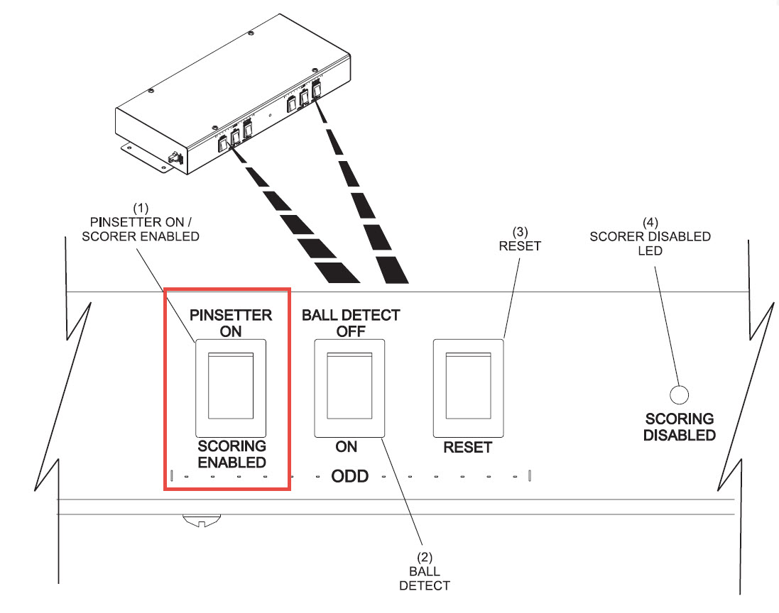
String Pinsetter Interface has had the "Pinsetter On / Scoring Enabled" switch turned to "Pinsetter On" while the pinsetter and scoring was in progress.
Solution:
  1. Turn the "Pinsetter On / Scoring Enabled" switch for that lane back to "Scoring Enabled" and then turn off the main power switch on the SES String Control box.
  2. Turn the main switch back on.
This will reset the SES electronics to see the pin fall data.


Applicable Files:
Related Information and Links:
Revision Date:
11/22/2016 - Released to KB

 
3.3.11. Tom England Control Box - Ball Elevator Motor Control
Title: Tom England Control Box - Ball Elevator Motor Control
Environment: 5-Pin String Machine
Applicable Version(s): Tom England Control Boxes
Issue: No power to Ball Elevator Motor when one only one machine of the pair is issued.
Cause:

Faulty Control Relay

Solution:

Located in the Tom England Control Box are two cube style relays that control power to the 5-Pin String machines original ball elevator motor. One relay powers on the motor when an odd lane is issued, and one relay for when the even lane is issued. These relays will be located side by side and inserted into a blue base relay holder.

If the motor does not come on when only one lane is issued, locate the two relays in the box and swap them. If the problem moves to the opposite machine and the motor will power up with the original problem machine the relay is defective.

Note: Keep in Mind that Tom England’s placement of the relays in the box may differ. They may be located at the top of the box, or the bottom of the box. Use the Photo attached to see how the relays look and have the customer locate where they are placed.


Applicable Files:
Related Information and Links:
3.3.12. V2 Slide-Out installation in Existing V1 Slide-Out Installations (360 String)
Environment:
360 Controller String Pin Pinsetter
Applicable Version(s):
V1 and V2 Slide-Outs for 360 Controller
Procedure:
See attachment
Applicable Files:
'V2 slide-out installation in existing V1 slide-out installations-edited2.pdf'
Related Information and Links:
Revision Date:
03/09/2022 - Released to KB

 
3.4. Pinsetter Lighting Systems
3.4.1. Brunswick Multi-Colored LED Lighting
Environment:
Brunswick Multi-Colored LED Lighting
Applicable Version(s):
All
Document Description:
The Multi-colored pin deck light is DMX controlled. The DMX Controller we provided is pre-programmed with 26 light shows for the pin deck lights. The 26 programs allow the DMX controller to operate the pin deck lights in a stand-alone environment, without a computer interface.
 
A DMX lighting tech, with a computer and DMX software, can program the DMX controller to operate the pin deck lights and other DMX controllable devices. The 26 pre-programmed light shows will not work with add on devices. They only work with the pin deck light. This means that the DMX lighting tech will need to create the light shows for the pin deck lights, and any other DMX devices they add on.

Brunswick does not have any expertise in creating a DMX controllable lighting environment, especially in the creation of the light shows.

The controller is a DVC4 GOLD: Mini USB-DMX interface. 1 DMX OUT universe (512 channels) and 1 DMX IN/OUT universe (512 channels) -total Live Channels 1024.0. 128k stand alone memory. Works with DVC3 and DVC4 software. Delivered with a USB cable (no Ethernet). Power supply and plug adapter are also included. Compatible with Windows XP/VISTA/7/8/10 32/64-bit. It is pre-programmed to control the multi colored pin deck lights provided by Brunswick. 

The documentation inside the box from the manufacturer has this link to the manuals and information https://www.daslight.com/manuals/#/.
Software to program the controller can be found at https://www.daslight.com/download.htm.
It is pre programmed with 26 light shows for the pin deck light. See page 26 of the attached installation manual to change the preset programs.
If they choose to not use the controller we supplied and go with their own system I've attached the information on the pin deck lights so the DMX tech can address them.

To create light shows based on bowling events (strike, spare etc). SYNC (with a data package that can be purchased from Brunswick) can send out bowling event data over the network to a customer supplied DMX server. The DMX server will interpret the data and create the light shows that the DMX tech made. The DMX tech will also need to reach out to Brunswick to request information regarding the bowling data output for the bowling-based events prior to connecting the DMX lighting to the server. 

Applicable Files:

'Installation-Manual_LED-Pin-Light_47-902714__r_9-12-18.pdf'

'DV4Gold-DMX-Controller.pdf'

'Omni_OS-8080_manual.pdf'

Related Information and Links:
Revision Date:
02/13/2019 - Released to KB.

 
3.5. Stop Errors Associated with Reed Switch Signal
Environment:
Pinsetter
Applicable Version(s):
GS series Pinsetters and Brunswick String Pinsetters
Issue:
Stop errors associated with reed switch signal.
Cause:
Reed switch resist failed to maintain 100 Ohms + or – 5%.
Solution:
See attachment
Applicable Files:
'Troubleshooting Faulty Reed Switch.pdf'
Related Information and Links:
Revision Date:
09/28/2018 - Released to KB

 
4. Scoring Systems